3-1
014–001867
Chapter 3
Installing and Removing VME
Option Boards
This chapter contains information and general instructions for removing and
installing VME option boards in an AViiON computer card cage. The information in
this chapter assumes you have planned and verified your configuration as described
in Chapter 1, and configured any new boards as described in Chapter 2.
Before you begin to install or remove a VME option board, you will need the
following:
•
A thorough understanding of the section “Avoiding ESD Damage” in Chapter 1.
•
The expanding and/or maintaining manuals for your system if you need to
jumper the backplane as noted in “Assigning Card Cage Slots” in Chapter 1.
•
Nonmagnetic needlenose pliers if you need to jumper the backplane.
•
A number 1 flat-blade screwdriver.
•
A medium Phillips screwdriver.
WARNING:
Unqualified personnel attempting to remove, install, or
service internal components or options in AViiON 5000, 6000,
7000, and 8000 series systems risk both personal injury and
damage to the system. Data General Corporation supports
the maintenance and expansion of these systems by qualified
Data General personnel only. Service by other than
Data General personnel may void product warranties. For
more information regarding Data General warranties, refer to
your Data General sales and field engineering contracts.
Card Cage Assembly
The card cage assembly in an AViiON computer system consists of a metal housing
with formed board slots and a backplane printed circuit board that attaches to the
metal housing. The card cage’s mechanical and electrical designs comply with the
specifications described in The VMEbus Specification manual.
The formed slots on computer systems covered in this manual align two Eurocard
6U form factor boards (233 mm x 160 mm) to the connectors on the backplane board.
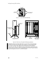
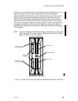
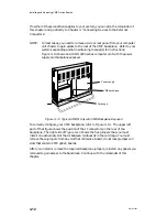
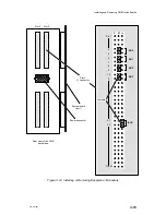
Figure 3–1 shows a typical 6U board assembly. Figure 3–2 shows the location of the
VMEbus options card cages in the rear of typical AViiON computers.
Содержание AViiON 5000 Series
Страница 2: ......
Страница 6: ......
Страница 12: ...Preface x 014 001867 ...
Страница 86: ...Configuring VME Option Boards 2 52 014 001867 ...
Страница 144: ...Connecting External Devices to VME Option Boards 4 44 014 001867 ...
Страница 150: ...VME Backplane Connector Signals and Power Distribution A 6 014 001867 ...
Страница 196: ...Assigning VME Data Bus and Interrupt Priorities E 10 014 001867 ...
Страница 206: ......
Страница 209: ...Cut here and insert in binder spine pocket Setting Up and Installing VMEbus Options in AViiON Systems 014 001867 03 ...
Страница 210: ...Appendix Title ...

