v
014–001867
Preface
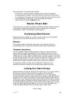
This manual contains information that you will need to add VMEbus-related
hardware to your AViiON
system. It supplements your system’s setting up,
expanding, and maintaining manuals that list the VME options supported by your
particular model. You should also refer to your most recent Technical Notices,
software updates, and Release Notices for current information.
The first three chapters in this manual describe how to add and replace optional
controllers and adapters that communicate with your system’s central processing
unit over a VMEbus. Chapter 4 describes how to connect devices to the VME
controllers and adapters supported by Data General—most readers will need this
chapter alone.
WARNING:
Unqualified personnel attempting to remove, install, or
service internal components or options in AViiON 5000, 6000,
7000, and 8000 series systems risk both personal injury and
damage to the system. Data General Corporation supports
the maintenance and expansion of these systems by qualified
Data General personnel only. Service by other than
Data General personnel may void product warranties. For
more information regarding Data General warranties, refer to
your Data General sales and field engineering contracts.
Organization of This Manual
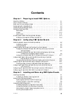
This manual is organized as follows:
Chapter 1
Provides configuration rules and guidelines. It also describes
supported boards and how to avoid electrostatic discharge (ESD)
damage to your equipment. You should read this chapter carefully
before you begin to replace or add VME options.
Chapter 2
Describes how to install and remove jumpers and change switch
settings on printed circuit boards. Provides tables of settings for
AViiON computer systems running the DG/UX
operating system.
Chapter 3
Describes how to install or remove a VME board in an AViiON
computer.
Chapter 4
Describes how to connect external devices such as terminals,
printers, modems, and LAN transceivers to your VME controller(s).
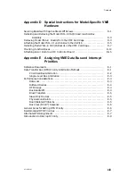
Appendix A
Shows the pin numbers and lists the VMEbus signals for the J1
and J2 backplane connectors.
Содержание AViiON 5000 Series
Страница 2: ......
Страница 6: ......
Страница 12: ...Preface x 014 001867 ...
Страница 86: ...Configuring VME Option Boards 2 52 014 001867 ...
Страница 144: ...Connecting External Devices to VME Option Boards 4 44 014 001867 ...
Страница 150: ...VME Backplane Connector Signals and Power Distribution A 6 014 001867 ...
Страница 196: ...Assigning VME Data Bus and Interrupt Priorities E 10 014 001867 ...
Страница 206: ......
Страница 209: ...Cut here and insert in binder spine pocket Setting Up and Installing VMEbus Options in AViiON Systems 014 001867 03 ...
Страница 210: ...Appendix Title ...


