Configuring VME Option Boards
2-21
014–001867
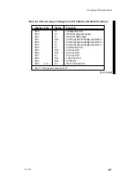
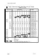
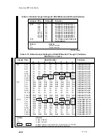
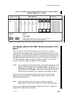
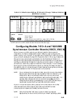
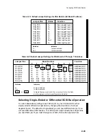
Table 2–14 Default Jumper Settings, VTC Boards 0 Through 7 Address Variations
(DG/UX 5.4.1 or earlier)
Jumper Pins
Board Number
Function
0
1
2
3
4
5
6
7
E3
1–2
In
In
In
In
In
Out
Out
Out
Address bit 31
3–4
Out
Out
Out
Out
Out
Out
Out
Out
Address bit 30
5–6
Out
Out
Out
Out
Out
Out
Out
Out
Address bit 29
7–8
In
In
In
In
In
In
In
In
Address bit 28
9–10
In
In
In
In
In
In
In
In
Address bit 27
11–12
In
In
In
In
In
In
In
In
Address bit 26
13–14
In
In
In
In
In
Out
Out
Out
Address bit 25
15–16
In
In
In
In
In
Out
Out
Out
Address bit 24
Notation
Indicates
In
Jumper installed
Out Jumper
removed
In
or
Out
Jumpers that you must install (In) or remove (Out) in the field;
all other jumpers are factory-configured, as indicated.
NOTE:The E4, E5, and E14 jumpers shown in the previous table also apply.
Configuring Models 7413–A and 7428 VME
Synchronous Controller Boards (VSC/3, VSC/3i)
When you receive a VME synchronous controller board from Data General
Corporation, it is factory configured for board 0 default jumper settings and for
DG/UX revision 5.4.1 or earlier. If the board you are installing is not the first of its
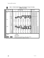
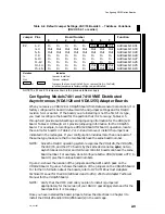
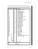
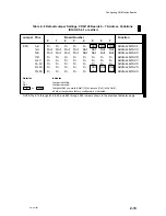
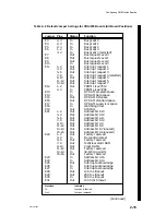
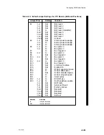
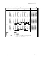
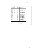
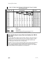
type, you must reconfigure the board for the position that it is to occupy. Tables 2–15
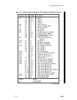
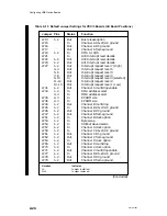
through 2–16 provide jumpering information for the VSC/3 board. Tables 2–17
through 2–18 provide jumpering information for the VSC/3i board. For example, to
reconfigure a VAC/3 board to board 1, locate the column for board 1 in Table 2–16
and remove or install the jumpers as indicated in the rectangles. You can configure
the three ports on the VSC/3i board to support any of these interfaces: RS–232–C,
RS–449/530, V.35, or X.21 (see discussion under heading Changing the Synchronous
Electrical Interface for VSC/3i Channels later in this section).
NOTE:
If your configuration includes more than one synchronous communication
board, make certain that each board (whether VSC/3 or VSC/3i) in your
configuration has a unique board number even if your synchronous
communication software uses different device names for each board. For
example, SNA software refers to its controller as an sdcp, and X.25
communications software uses ssid, but if your system includes both, it
nonetheless requires that they have different board numbers.
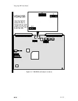
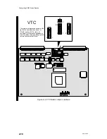
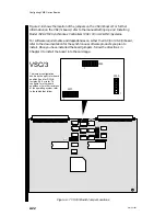
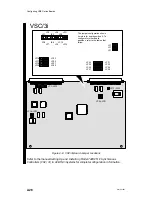
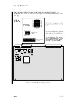
Figure 2–7 shows the location of the jumpers on the VSC/3 board. For further
information about the VSC/3 board, refer to the manual VMEbus Data
Communications Processor (DCP-8820) Technical Manual.
NOTE:
Verify that the VME controller you plan to install is jumpered
appropriately for the current revision of your DG/UX operating system.
Содержание AViiON 5000 Series
Страница 2: ......
Страница 6: ......
Страница 12: ...Preface x 014 001867 ...
Страница 86: ...Configuring VME Option Boards 2 52 014 001867 ...
Страница 144: ...Connecting External Devices to VME Option Boards 4 44 014 001867 ...
Страница 150: ...VME Backplane Connector Signals and Power Distribution A 6 014 001867 ...
Страница 196: ...Assigning VME Data Bus and Interrupt Priorities E 10 014 001867 ...
Страница 206: ......
Страница 209: ...Cut here and insert in binder spine pocket Setting Up and Installing VMEbus Options in AViiON Systems 014 001867 03 ...
Страница 210: ...Appendix Title ...

