Installing and Removing VME Option Boards
3-12
014–001867
If neither of these conditions applies to your system, you can skip the remainder of
this chapter and go directly to Chapter 4, “Connecting Devices to the External
Connectors.”
NOTE:
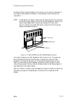
In most cases, you need to remove a side or rear panel from your computer
unit chassis to gain access to the rear of the VME backplane. Refer to your
system’s expanding and/or maintaining manual(s) for instructions;
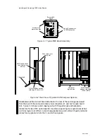
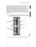
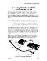
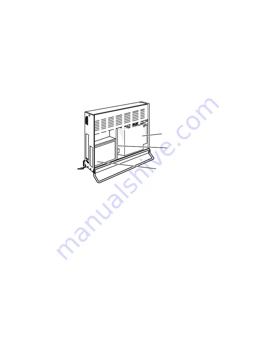
Figure 3–13 shows an AViiON 4000 series computer unit with the power
supply and backplane exposed.
Power supply
VME backplane
Card cage
Figure 3–13 Typical AViiON Unit with VME Backplane Exposed
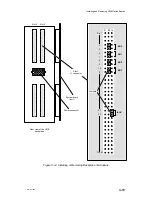
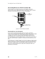
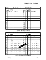
To correctly configure your VME backplane, refer to Figure 3–14. The upper left
part of that figure shows the position of the J1 connectors on the rear of the
backplane. The right side of Figure 3–14 shows the five jumpers that you must
install on each empty slot that is between two boards in the card cage. You must
remove these jumpers from any slot that contains a board; do not leave jumpers on
slots that contain VME option boards.
After you install or remove the required backplane jumpers, reinstall any panels you
removed to gain access to the backplane. Continue with the remainder of this
chapter.
Содержание AViiON 5000 Series
Страница 2: ......
Страница 6: ......
Страница 12: ...Preface x 014 001867 ...
Страница 86: ...Configuring VME Option Boards 2 52 014 001867 ...
Страница 144: ...Connecting External Devices to VME Option Boards 4 44 014 001867 ...
Страница 150: ...VME Backplane Connector Signals and Power Distribution A 6 014 001867 ...
Страница 196: ...Assigning VME Data Bus and Interrupt Priorities E 10 014 001867 ...
Страница 206: ......
Страница 209: ...Cut here and insert in binder spine pocket Setting Up and Installing VMEbus Options in AViiON Systems 014 001867 03 ...
Страница 210: ...Appendix Title ...

