Preparing to Install VME Options
1-9
014–001867
CAUTION: On six–slot (five user slots) AViiON systems, slot 2 (first user slot) is
restricted exclusively to the use of Data General Corporation qualified
VME controller boards. On these systems, the J2 connector on slot 2 has
reserved areas with power and ground potentials that could cause
damage to unqualified VME boards (See Table A–2, Appendix A).
On AViiON systems, the VMEbus originates on either a system board or a VME
system control board, both of which include circuitry implementing and managing
the entire bus. A factory-installed printed circuit board (called the VME backplane)
extends the bus to one or more removable printed circuit boards built to VME
specifications. We refer to the enclosure that holds these boards as the VME card
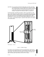
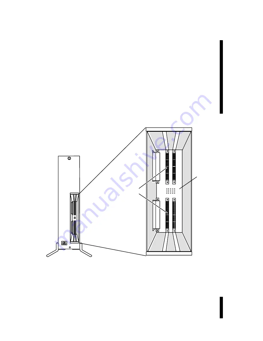
cage. Figure 1–3 shows the card cage in a typical AViiON computer with connectors
for two option boards.
VME
backplane
AViiON computer — rear view
VME card cage
(exposed)
Option board
connectors
Figure 1–3 VME Card Cage
The VMEbus carries signals between the host logic board (either system board or
VME system control board) and the VME controller boards in the VME card cage. On
some systems, a cable with associated repeaters can extend the bus between the
system’s chassis, system logic chassis, and user VME card cage.
Содержание AViiON 5000 Series
Страница 2: ......
Страница 6: ......
Страница 12: ...Preface x 014 001867 ...
Страница 86: ...Configuring VME Option Boards 2 52 014 001867 ...
Страница 144: ...Connecting External Devices to VME Option Boards 4 44 014 001867 ...
Страница 150: ...VME Backplane Connector Signals and Power Distribution A 6 014 001867 ...
Страница 196: ...Assigning VME Data Bus and Interrupt Priorities E 10 014 001867 ...
Страница 206: ......
Страница 209: ...Cut here and insert in binder spine pocket Setting Up and Installing VMEbus Options in AViiON Systems 014 001867 03 ...
Страница 210: ...Appendix Title ...

