Preparing to Install VME Options
1-8
014–001867
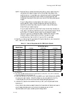
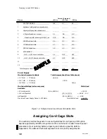
Current (Amperes)
Device
+5 V dc
+12 V dc
–12 V dc
0
SYSTEM BOARD
14.4
0.7
0.1
1
Keyboard (with graphics console only)
2
Mouse (with graphics console only)
3
4 Mbyte Memories: 1 active;
3.1
NA
NA
4
3 inactive (idle ) drawing 0.24 (5V), ea
0.72
NA
NA
5
320-Mbyte hard disk
2.0
3.3
NA
6
179-Mbyte hard disk
1.1
1.4
NA
7
QIC-150 tape drive
1.5
1.5
NA
8
VME options:
9
slot 1 – VSC/3 sync controller
3.4
0.07
0.07
10
slot 2 – VAC/16 async controller
4.5
0.25
0.25
11
12
Total Amperes Used
30.72
7.22
0.42
Power Supply
Maximum Amperes Available
Total Amperes Used (from Table above)
+ 5 V Total
= 37.0 amps
30.72 A
+12 V Total
= 10.0 amps
7.22 A
–12 V Total = 1.0 amps
0.42 A
Maximum Wattage (volts x amperes)
Watts Used
Available
+5 V wattage total
(5 V x 30.72 A)
= 152.36
+12 V wattage total
(12 V x 7.22 A)
= 86.64 –12 V
wattage total
(12 V x 0.42 A)
= 5.04
Maximum Power Supply Output = 330 Watts
Total Watts Used
= 244.04
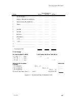
Figure 1–2 Sample Current and Power Calculation Form
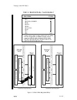
Assigning Card Cage Slots
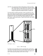
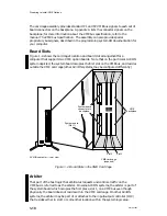
This section provides the general rules and guidelines for configuring VME option
boards supported by AViiON computers. Use this information to determine the exact
placement of your option(s) before jumpering and installing boards. Refer to
Appendix E for a detailed technical explanation of slot priority assignments.
Содержание AViiON 5000 Series
Страница 2: ......
Страница 6: ......
Страница 12: ...Preface x 014 001867 ...
Страница 86: ...Configuring VME Option Boards 2 52 014 001867 ...
Страница 144: ...Connecting External Devices to VME Option Boards 4 44 014 001867 ...
Страница 150: ...VME Backplane Connector Signals and Power Distribution A 6 014 001867 ...
Страница 196: ...Assigning VME Data Bus and Interrupt Priorities E 10 014 001867 ...
Страница 206: ......
Страница 209: ...Cut here and insert in binder spine pocket Setting Up and Installing VMEbus Options in AViiON Systems 014 001867 03 ...
Страница 210: ...Appendix Title ...


