


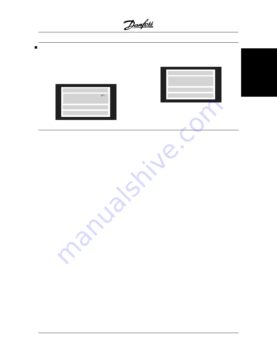
Warnings
The display flashes between normal state and warn-
ing. A warning comes up on the first and second line
of the display. See examples below. If parameter 027
is set to line 3/4, the warning will be shown in these
lines if the display is in read-out state 1-3.
SETUP
1
NO MOTOR
WARN. 3
Alarm messages
The alarm comes up in the 2. and 3. line of the display,
see example below:
ALARM:12
SETUP
1
TRIP (RESET)
TORQUE LIMIT
WARNING 1
Under 10 Volts (10 VOLT LOW):
The 10 Volts voltage from terminal 50 on the control
card is below 10 Volts.
Remove some of the load from terminal 50, as the 10
Volts supply is overloaded. Max. 17 mA/min. 590
.
WARNING/ALARM 2
Live zero fault (LIVE ZERO ERROR):
The current signal on terminal 60 is less than 50% of
the value set in parameter 315
Terminal 60,min. scal-
ing.
WARNING/ALARM 3
No motor (NO MOTOR):
The motor check function (see parameter 122) indi-
cates that no motor has been connected to the output
of the frequency converter.
WARNING/ALARM 4
Phase fault (MAINS PHASE LOSS):
A phase is missing on the supply side or the mains
voltage imbalance is too high.
This message can also appear if there is a fault in the
input rectifier on the frequency converter.
Check the supply voltage and supply currents to the
frequency converter.
WARNING 5
Voltage warning high
(DC LINK VOLTAGE HIGH):
The intermediate circuit voltage (DC) is higher than the
overvoltage limit of the control SYSTEM. The frequen-
cy converter is still active.
WARNING 6
Voltage warning low (DC LINK VOLTAGE LOW):
The intermediate circuit voltage (DC) is below the un-
dervoltage limit of the control SYSTEM. The frequency
converter is still active.
WARNING/ALARM 7
Overvoltage (DC LINK OVERVOLT):
If the intermediate circuit voltage (DC) exceeds the in-
verter overvoltage limit (see table), the frequency con-
verter will trip after the time set in parameter 410 has
passed.
Furthermore, the voltage will be stated in the display.
The fault can be eliminated by connecting a brake re-
sistor (if the frequency converter has an integral brake
chopper, EB or SB) or by extending the time chosen
in parameter 410. In addition,
Brake function/overvolt-
age control
can be activated in parameter 400.
VLT
®
5000 Series
MG.51.C5.22 - VLT
p
is a registered Danfoss trademark.
161
Messages
Содержание VLT 5000 Series
Страница 2: ...VLT 5000 Instruction Manual ...
Страница 3: ......
Страница 45: ...Mechanical dimensions cont VLT 5000 Series 42 MG 51 C5 22 VLT p is a registered Danfoss trademark ...
Страница 185: ...VLT 5000 Series 182 MG 51 C5 22 VLT p is a registered Danfoss trademark ...
Страница 186: ...VLT 5000 Series MG 51 C5 22 VLT p is a registered Danfoss trademark 183 EC EMC ...
Страница 196: ...RELATIVE VLT 5000 Series MG 51 C5 22 VLT p is a registered Danfoss trademark 193 List of functions ...
Страница 197: ...EXTERNAL PRESET VLT 5000 Series 194 MG 51 C5 22 VLT p is a registered Danfoss trademark ...
Страница 198: ...References VLT 5000 Series MG 51 C5 22 VLT p is a registered Danfoss trademark 195 List of functions ...
Страница 202: ...VLT 5000 Series MG 51 C5 22 VLT p is a registered Danfoss trademark 199 List of functions ...
Страница 217: ...VLT 5000 Series 214 MG 51 C5 22 VLT p is a registered Danfoss trademark ...
Страница 238: ...Rev 2006 12 12 www danfoss com drives 175R5271 MG51C522 MG51C522 MG51C522 VLT 5000 Instruction Manual ...
Страница 239: ......