CY8CKIT-025 PSoC® Precision Analog Temperature Sensor Expansion Board Kit Guide, Doc. # 001-65791 Rev. *J
32
Example Projects
The following sections provide a detailed description of these example projects.
5.2
Tempsense
This example project demonstrates high-precision, high-accuracy, multi-channel temperature sens-
ing using PSoC.
5.2.1
Project Description
This project displays the temperature measured using a thermocouple, IC sensor, thermistor, RTD,
and two diodes. It also provides steps to calibrate the RTD, diode, and IC. The user interface of this
example is controlled by two CapSense
®
buttons, a CapSense slider, two mechanical push buttons,
and a character LCD.
When the example project for CY8CKIT-030 is programmed, the LCD displays a welcome message
for one second. It then displays the temperature from the thermocouple, which is the first item in the
user selectable menu. CapSense buttons P5_5 and P5_6 act as the scroll down and scroll up menu
buttons, respectively. A mechanical switch connected to P6_1 is used to proceed through various
calibration steps. A CapSense slider is used to set the calibration temperature.
The menu has the following items:
■
Thermocouple temperature display
■
IC temperature display
■
Thermistor temperature display
■
RTD temperature display
■
Diode1 temperature display
■
Diode2 temperature display
■
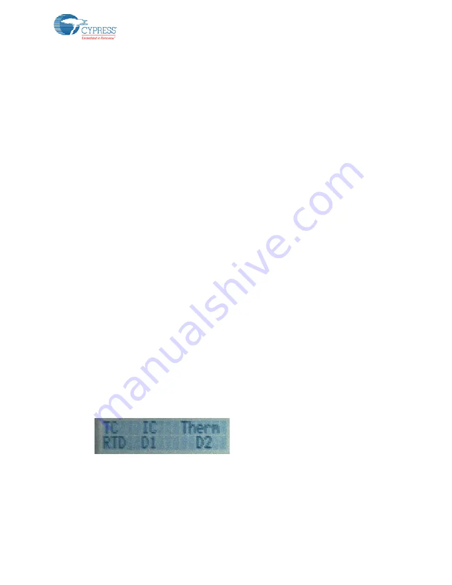
Simultaneous temperature display labels (see
)
■
Simultaneous temperature display from all 6 sensors (see
)
■
Calibrate RTD temperature
■
Calibrate Diode1 temperature
■
Calibrate Diode2 temperature
■
Calibrate IC sensor temperature
In the simultaneous display, the first row displays the temperature of the thermocouple, IC, and
thermistor. The second row displays the temperature of the RTD, diode 1, and diode2, as shown in
.
Figure 5-3. Simultaneous Temperature Display Labels


