CY8CKIT-025 PSoC® Precision Analog Temperature Sensor Expansion Board Kit Guide, Doc. # 001-65791 Rev. *J
21
Kit Operation
WARNING:
Static discharges from the human body can easily reach very high voltages in the order
of kV. Such voltages can damage the PSoC device on the development kit. Ensure that you dis-
charge any static before touching the hardware. Follow these steps to avoid any unwanted behavior
on the board:
1. Power off the kit before making any connections
2. Connect the CY8CKIT-025 EBK to the development kit being used
3. Power on the development kit
3.3
Temperature Sensors
The PSoC Precision Analog Temperature Sensor EBK supports the following temperature sensors:
■
Thermocouple
■
Thermistor
■
Resistive Temperature Detector (RTD)
■
Diode
■
DS600 IC
3.3.1
Thermocouple
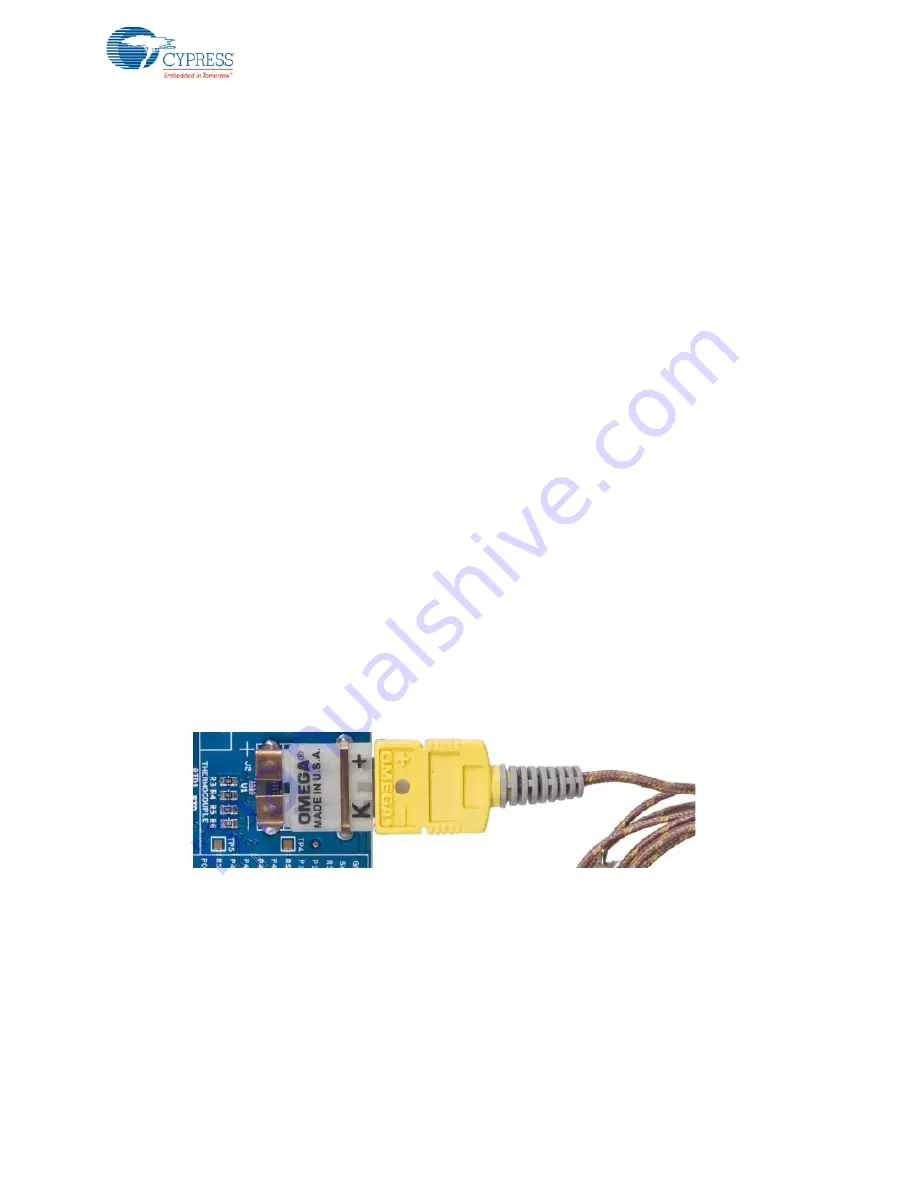
The board has a K-type thermocouple socket, PCC-SMP-K-5. The K-type Omega thermocouple,
5SRTC-GG-K-20-36, is shipped with the kit. It complies with the ASTM special limits of error toler-
ance standard. IC DS600 is provided on the board for cold junction compensation. The thermistor on
the board can also be used for cold junction compensation. Because the onboard thermistor is not
calibrated, the IC (DS600) is provided for cold junction compensation.
provides an example project that demonstrates how to use the therm-
istor for cold junction compensation. For more details about the thermocouple 5SRTC-GG-K-20-36
and IC DS600, see their datasheets in the following location:
<Install_Directory>\PSoC Precision Analog EBK\<version>\Documentation\DataSheet
.
While connecting the thermocouple to the connector, make sure the markings in the thermocouple
match those of the connector.
Figure 3-5. Thermocouple
3.3.2
Thermistor
The board has a NCP18XH103F03RB (NTC) thermistor. It has a 1 percent tolerance (10 k ± 1%) at
25 °C. For more details about the sensor, see its datasheet in the following location:
<Install_Directory>\PSoC Precision Analog EBK\<version>\Documentation\DataSheet
You can also plug an external thermistor in terminal J7. The choice between using the internal and
external thermistor is made using jumper J5. The jumper is inserted on header position 1–2 for using
an external thermistor and on header position 2–3 for using the internal (onboard) thermistor. The
silk indicates the jumper positions for internal and external thermistors.


