CY8CKIT-025 PSoC® Precision Analog Temperature Sensor Expansion Board Kit Guide, Doc. # 001-65791 Rev. *J
71
Example Projects
Figure 5-24. CY8CKIT-030 PSoC 3 DVK Power Jumpers
3. Ensure that POT_PWR is enabled by installing a jumper on J30.
Figure 5-25. CY8CKIT-030 PSoC 3 DVK Potentiometer Power
CAUTION:
The TME EBK plugged into port D of the CY8CKIT-030 DVK uses the SWD/JTAG pro-
gramming pins for fan control as well. Due to this pin sharing, the TME EBK should not be attached
to the CY8CKIT-030 DVK while programming the PSoC 3 device using MiniProg3 or DVKProg3 pro-
grammer. After the programming is complete, remove the programmer from the programming
header on the PSoC 3 DVK and then attach the TME EBK to port D. Due to pin sharing, debugging
the project is also not possible because it uses the same programming pins.
5.4.2.1.2
CY8CKIT-001 PSoC DVK
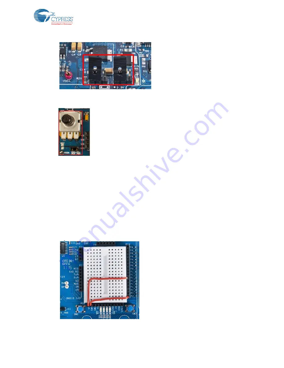
1. In the pin header/breadboard area of the PSoC DVK base board, use jumper wires to make the
following connections:
❐
VR to P1_2
❐
SW1 to P2_7
Figure 5-26. CY8CKIT-001 PSoC DVK Breadboard


