CY8CKIT-025 PSoC® Precision Analog Temperature Sensor Expansion Board Kit Guide, Doc. # 001-65791 Rev. *J
74
Example Projects
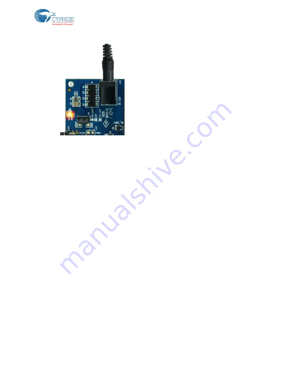
Figure 5-33. External Power Supply Connected
5.4.2.2
Run Thermal Management System Firmware
5.4.2.2.1
CY8CKIT-030 PSoC 3 DVK
The steps to run the example firmware on CY8CKIT-030 are:
1. Make the hardware connections on the CY8CKIT-030 DVK, as explained in
.
2. Attach a USB cable from the PC to the PSoC 3 DVK program/debug USB port (use J1, the USB
connector closest to the corner of the board). Ensure that the TME EBK is not attached to the
PSoC 3 DVK before attaching the USB cable for programming.
3. Open the ThermalManagementSystem_030_050 project using PSoC Creator and select
Debug
> Program
to program the PSoC.
4. Detach the USB cable; if the DVK is powered by external power supply, disconnect power supply
to the DVK as well.
5. Connect the CY8CKIT-025 EBK and TME EBK to the DVK, as shown in
.
6. Power the PSoC 3 DVK and the TME EBK, as shown in
.
7. Press the
Reset
(SW1) button on the PSoC 3 DVK to run the newly programmed firmware
image.
8. On reset, the LCD displays a welcome message and starts with the Zone 1 temperature reading
and the corresponding temperature calculation algorithm. The desired and actual fan speeds cor-
responding to that zone are also displayed.
9. Use the push button SW2 to view the different zone characteristics.
5.4.2.2.2
CY8CKIT-001 PSoC DVK
The steps to run the example firmware on CY8CKIT-001 are:
1. Make the hardware connections on the CY8CKIT-001 DVK, as explained in
2. Apply 12 VDC power to the PSoC DVK.
3. Attach the MiniProg3 device, first to a USB port on the PC and then to the PROG port on the
CY8CKIT-009 PSoC 3/CY8CKIT-010 PSoC 5LP processor module. Ensure that the TME EBK is
not attached to the PSoC 3 DVK before attaching the USB cable for programming.


