Programmable DC Power Supply (with Solar Array Simulation) 62000H Series
Operating & Programming Manual
5-24
the bit position enable bits are
logically ORed to cause Bit 6 (the Master
Summary Status Bit)
of the Status Byte register to be set. See Status
Byte register for detail description.
Syntax:
*SRE <NR1>
Parameter:
0 to 255
Example:
*SRE 20
Enable the CSUM and MAV bit of the Service Request.
Query Syntax: *SRE?
Return Parameter: <NR1>
Query Example: *SRE?
Return the current setting of Service Request Enable.
*STB?
Read Status Byte Query
Type:
Device status
Description:
This query reads the Status Byte register. Note that the MSS
(Master
Summary Status) bit instead of RQS bit is returned in
Bit 6. This bit
indicates if the High Slew Rate Load has at least one
reason for
requesting service. *STB? does not clear the Status
Byte register, which
is cleared only when subsequent action has
cleared all its set bits.
Query Syntax:
*STB?
Return Parameter: <NR1>
Query Example: *STB?
Return the contents of Status Byte.
Return Example: 20
1.
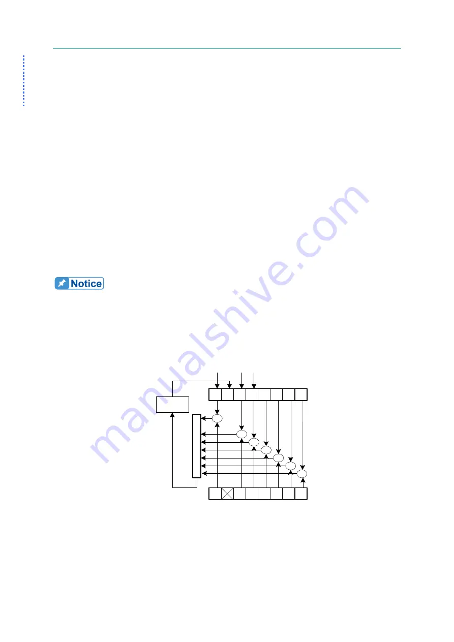
Status Byte Register:
The Status Byte Register is composed of eight bits that summarize
an overlaying status data structure. The Status Byte Register can
be read using *STB? to return a decimal expression of the register
contents (which means the total byte weight of all the byte set to
“1”.)
0
1
2
3
RQS
7
Status Bytes
Register Read
by *STB?
0
1
2
3
4
5
7
Set Service Request
Enable Register by
*SRE
L
ogica
l
OR
&
&
&
&
&
&
&
Service
Request
ESB MAV
Status Summary Message
Figure 5-1


