11. Wiring Limit, Estop and Fault Inputs
1. Limit switch, Estop, Spindle Fault & Lube Fault PLC input wiring
All inputs used
for Limit switches, Estop, Spindle Fault & Lube Fault must be wired in Normally closed
configuration. The switch should be closed when the machine is in it's operational state.
Wiring any of these inputs in a Normally Open configuration is dangerous as there is no
way to stop the machine in the event that a wire breaking. It also prevents noise from
causing spurious faults because the signal is being electrically held at the operational
level.
The I/O configuration on every machine is different. While the examples below assume
dry contact type switches and utilize 12VDC, your machine may utilize different voltage
levels and different type devices devices such npn, or pnp proximity sensors. If your
devices are proximity sensors, they MUST be 3-wire sensors, 2-wire sensors will not
work reliably. Make sure the SIPS you installed in section 8 match the voltage levels for
your devices as voltage levels.
Failure to install the proper SIPS to match the voltage levels being used will damage the
GPIO4D
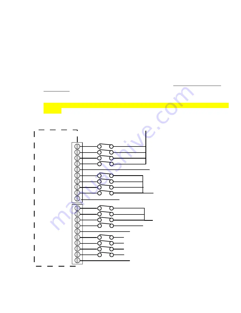
Connect your limit switches, lube fault spindle fault & Estop as shown:
Spindle Fault -NC Relay in VFD or OL Spin contacter
Lube Fault -NC Switch on Lube Pump
IN1
IN2
IN3
IN4
COM 1-4
IN5
IN6
IN7
IN8
COM 5-8
12COM
12VCOM
+12VDC
GPIO4D Board
IN9
IN10
IN11
IN12
COM 9-12
IN13
IN14
IN15
IN16
COM13-16
12COM
12VCOM
+12VDC
X- Limit
X+ Limit
Y- Limit
Y+ Limit
Z- Limit
Z+ Limit
W- Limit
W+ Limit
EStop
+12VDC
Содержание GPIO4D
Страница 38: ...16 Wiring Auxiliary Sub systems 3 Spindle Wiring Spindle Contactor Wiring...
Страница 39: ...16 Wiring Auxiliary Sub systems 4 Spindle Inverter Wiring AutomationDirect GS2...
Страница 59: ...12 Counts differ on homing 13 Option not available 14 Parameter missing 15 Position error 16 FPWOM...


