15. Configure motors, encoders and limit switches in software
1. Configure your servo amplifiers for velocity mode and check the PID values in
CNC11 BEFORE testing motor movement.
Do NOT try to move your motors until
instructed to do so below.
Before powering up the system, push your Estop switch in and
leave it in. Power up your system. Start the CNC11 software by double clicking on the
CNC11 Mill icon on your desktop. After the MPU11 has initialized, press F10 to continue to
the main screen. Navigate to the PID Config screen as follows:
F1-Setup->F3-Config (pw=137)->F4 PID->F1-PID Config
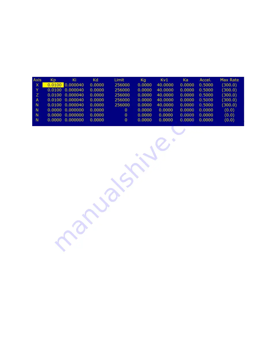
Set the PID for all axes as shown:
Kp = .01 Ki = .00004 Kd = 0 Limit 256000 Kg = 0 Kv1 = 40 Ka = 0 Accel = .500
2. Confirm Encoder Feedback on all axes
With the Estop pushed in, enter the PID menu
as you did in section 12.2 manually rotate each motor while watching the abs_pos field for
that axis and confirm that you have smooth feedback on all axes and that X updates the
X DRO, Y updates Y DRO etc... If any of your encoders do not update as expected, please
review the encoder parameters above (sec 12.2) and/or encoder wiring and MPU11
connection. If all your encoders update smoothly, manually move all axes to the center of
their travel to provide safe clearance when the motors are tested under power.
3. Release Estop and press Cycle start (alt-s) set home
Carefully release the Estop
switch, being ready to press it again quickly if unexpected movement occurs.
4.
Configuring movement
Confirm that the feedrate override is set to 100% and enter
the following command in MDI:
Remember -be ready to press Estop if unexpected/violent movement occurs
G92 X0 Y0 Z0
Then press Cycle Start or press alt-s
When the DRO displays 0's for all 3 axes, enter this command in MDI:
G1 X.1 F1
Then press Cycle Start or press alt-s
If the move completes normally, command it to return to zero as shown below:
G1 X0 F1
Then press Cycle Start or press alt-s
Perform these moves for all axes. If any axis jumps, anf faults either with a stall or position
error, try reversing the wires on Analog Out(+) and Analog Out Com for that axis and retry.
Содержание GPIO4D
Страница 38: ...16 Wiring Auxiliary Sub systems 3 Spindle Wiring Spindle Contactor Wiring...
Страница 39: ...16 Wiring Auxiliary Sub systems 4 Spindle Inverter Wiring AutomationDirect GS2...
Страница 59: ...12 Counts differ on homing 13 Option not available 14 Parameter missing 15 Position error 16 FPWOM...


