


4. The differential gain has the least effect on system
performance and should be left at the default setting of
zero (0).
5. Response times will be limited by changes in the fluid
mechanics of the system. It will take longer to achieve
requested flow rate as fluid viscosity increases or fluid
supply pressure de-creases. In other words, the same
response cannot be achieved for a 50 sec, Zahn #2 ma-
terial as for a 20 sec, Zahn #2 material given the same
fluid supply pressure and fluid control components. This
is important to understand, especially for 2K systems.
It may be an advantage to purposely slow down the
response of the quicker reacting (thinner) fluid such
that it will remain closer to that of the thicker fluid in 2K
systems during triggers or changes in the set point.
Other options are to decrease the supply pressure for
the thinner fluid or increase pressure for the thicker fluid.
6. "Reset Windup" condition. Reference "Trouble-shoot-
ing" in the "Maintenance" section. Reset windup is a
condition when the controller does not have enough
strength to reduce the error back to zero. This occurs
due to unusual restrictions in the fluid control devices
or fluid lines and indicates that the system is not tuned
properly or there is a problem. If the actual fluid flow
is less than the requested flow (minus the dead band
value), the controller will continue to increase the output
until it reaches the maximum allowable fluid regulator
Quick triggering applications: For applications requiring
multiple, short trigger cycles, more stable response
can typically be obtained by adjusting the Kp down to
approximately 75-100, while adjusting the Ki to approx-
imately 1000-2500.
2. The Integral gain is probably the most important set-
ting and has the greatest overall impact on response
behavior associated with the fluid flow control system.
This parameter can also be adjusted through a relatively
large range without creating instability.
3. The Proportional gain can improve system response,
especially for large set point changes, but care should be
taken not to increase by more than approximately 25%
of the default setting. The system can easily become
unstable and go into oscillation if adjusted to high.
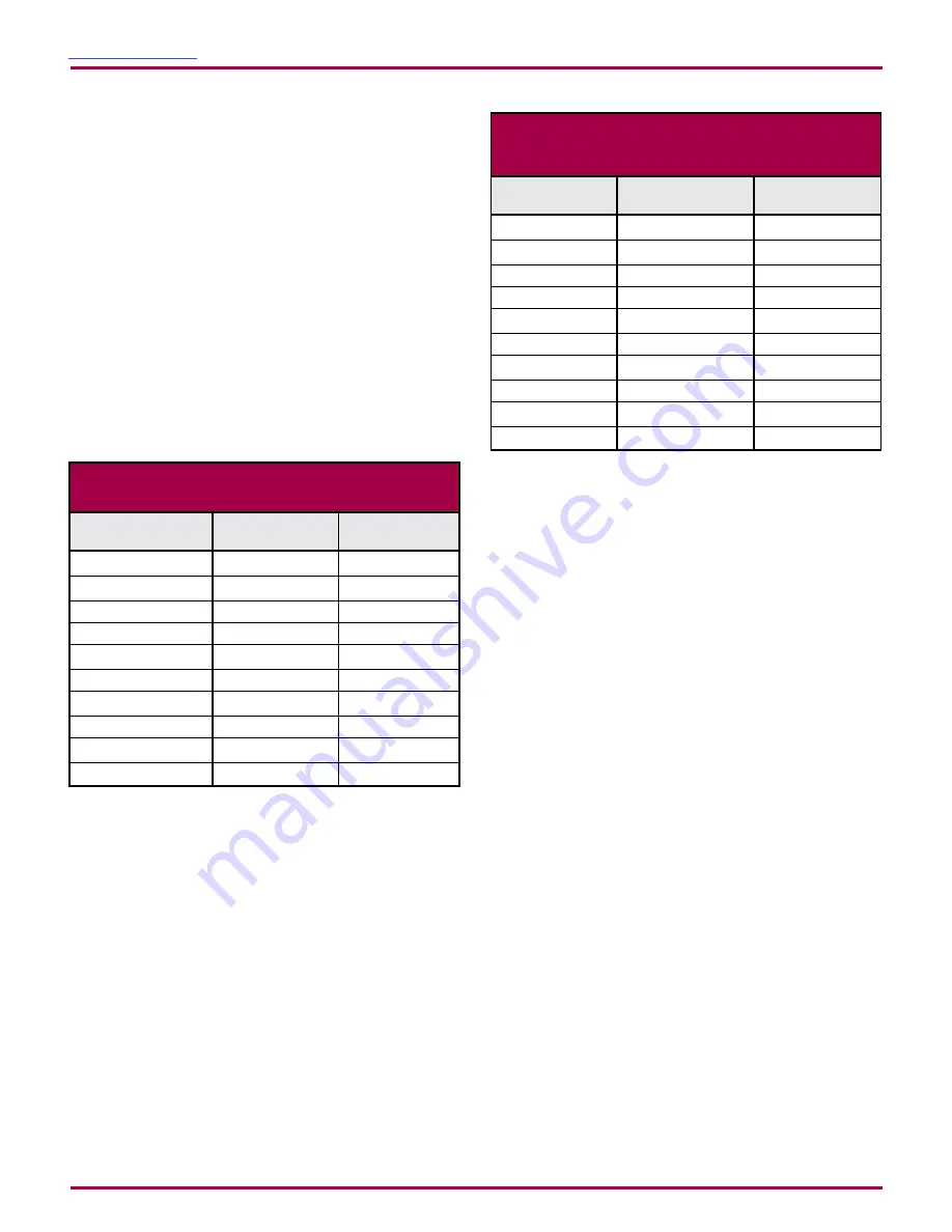
MVR #2
10
1200
MVR #3
15
1000
MVR #4
20
800
DR1, 1:1
50
1000
DR1, 1:2
45
1200
DR1, 1:3
40
1400
DR1, 1:4
35
1600
DR1, 1:6
30
1800
DR1, 1:8
25
2000
DR1, 1:10
20
2000
DEFAULT CONTROL PARAMETERS
Fluid Regulator
Kp
Ki
MVR #2
0-500
600-2400
MVR #3
0-500
500-2000
MVR #4
0-500
400-1600
DR1, 1:1
0-500
500-2000
DR1, 1:2
0-500
600-2400
DR1, 1:3
0-500
700-2800
DR1, 1:4
0-500
800-3200
DR1, 1:6
0-500
900-3600
DR1, 1:8
0-500
1000-4000
DR1, 1:10
0-500
1100-4400
Fluid Regulator
Kp Typical Range Ki Typical Range
TYPICAL RANGES FOR
CONTROL PARAMETERS
LN-9400-00-R11 (08/2018)
55 / 96
www.carlisleft.com
PARTS IDENTIFICATION
Содержание Ransburg DynaFlow 77376
Страница 13: ...Figure 1 Block Diagram Return To Contents LN 9400 00 R11 08 2018 13 96 www carlisleft com INTRODUCTION...
Страница 90: ...Fluid Panel Sheet 1 Return To Contents LN 9400 00 R11 08 2018 90 96 www carlisleft com APPENDIX...
Страница 91: ...Fluid Panel Sheet 2 Return To Contents LN 9400 00 R11 08 2018 91 96 www carlisleft com APPENDIX...
Страница 92: ...Fluid Panel Sheet 3 Return To Contents LN 9400 00 R11 08 2018 92 96 www carlisleft com APPENDIX...