CDE360 Vector Control AC Drive Chapter 6 Parameters Description
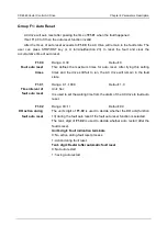
For example:
Determine the parameters to be displayed as below:
H0.01(LED display running parameters 1)
H0.02(LED display running parameters 2)
Bit0: running freq(Hz) (1)
Bit0: FI input freq(kHz) (1)
Bit2: Dc-link voltage(V) (4)
Bit2: load speed (4)
Bit3: output current(A) (8)
Bit4: output voltage(V) (16)
Bit6: output power(kW) (64)
Set the binary data:
H0.01 : 0000 0000 0101 1101B
H0.02 : 0000 0000 0000 0101B
Convert the binary data to decimal data:
H0.01 should be set to 93 (1+4+8+16+64 = 93)
H0.02 should be set to 5 (1+4 = 5)
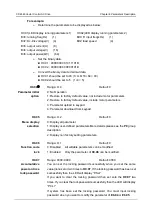
H0.04
①
Range: 0~4
Default: 0
Parameter initial
option
0: No Operation
1: Restore to factory default value, not include motor parameters
2: Restore to factory default value, include motor parameters
3: Parameter upload to keypad
4: Parameter download from keypad
H0.05
Range: 0~2
Default: 0
Menu display
selection
0: Display all parameter.
1: Display user-defined parameters.More details please see the
P0
group
description.
2: Display non factory setting parameters.
H0.06
Range: 0~1
Default: 0
Function code
lock
0: Disabled All writable parameters can be modified.
1: Enabled
Only the parameter of
H0.06
can be modified.
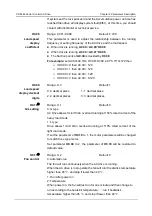
H0.07
Range: 0000~9999
Default: 0000
Accumulative
power on time
lock password
You can set the locking password successfully when you set the same
value(none zero) two times to
H0.07
. If the locking password has been set
successfully then the LED will display “P.Set”.
If you want to clear the locking password then set zero the
H0.07
two
times. If you clear the lock password successfully then the LED will display
“P.CLr”.
If system has been set the locking password, You must input locking
password when you want to modify the parameter of
Eb.04
or
Eb.05
.


