CDE360 Vector Control AC Drive Chapter 6 Parameters Description
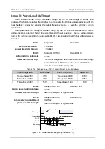
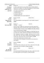
115% 125% 135% 145% 155% 165% 175%
80
Minimum allowed
overload time
40
15
5
2
Overload
coefficient
F0.07 = 0.93
F0.07 = 1.00
F0.07 = 1.10
Figure 6- 58 the inverse time-lag curve
F0.08
Range: 50~100
Default: 80
Motor overload
warning
coefficient
Unit: %
This function is used to generate a warning signal to the control system
via DO before motor overload protection. The larger the value is, the less
advanced the pre-warning will be.
To generate this warning signal, a DO terminal can be configured as
function 15 (motor overload pre-warning).
F0.09
Range: 0~1
Default: 0
Under load
protection
0: Disable 1: Enable
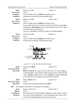
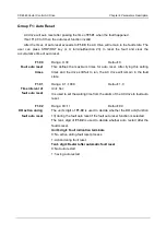
If the under load protection function is enabled, when the motor current is
less than the detection level (
F0.10
*
b0.08
) and the lasting time exceeds
the detection time (
F0.11
), protecting action will perform corresponding to
the setting of F0.20(unit's digit).
F0.10
Range: 0.0~100.0
Default: 40.0
Detection level of
Under load
Unit: %
It defines the detection level of under load.
F0.11
Range: 0.0~60.0
Default: 1.0
Detection time of
Under load
Unit: Sec
It defines the detection time of under load.
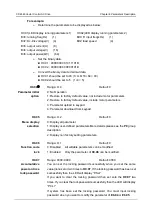
F0.12
Range: 0~2
Default: 0
Motor
temperature
Sensor type
It is used to select the type of motor temperature sensor.
0: No temperature sensor 1: PT100 2: PT1000
The signal of the motor temperature sensor needs to be connected to the
optional PT100/PT1000 extension card.
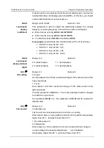
F0.13
Range: 0.0~200.0
Default: 120.0
Motor overheat
Unit:
℃


