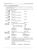
CDE360 Vector Control AC Drive Chapter 6 Parameters Description
are obtained from the linear switchover between the two groups of controller parameters, as
shown in Fig6-D4.
F2.02
F2.05
PI
参数
F2.00
F2.01
F2.03
F2.04
Figure 6- 23 Relationship between running frequencies and speed loop Kp & Ti
Note:
Improper controller parameter setting may cause overvoltage or over current trip.
d2.06
Range: 0 ~ 1
Default: 0
ASR integration
attribute
0: integral separation is invalid
1: integral separation is valid
If this parameter set to 1, integration of speed loop controller is valid only
when speed error is small. Therefore, speed overshot or oscillation can be
avoided when the Ti is small.
d2.07
Range: 50 ~ 120
Default: 100
Vector control
slip gain
Unit: %
Setting this parameter properly can improve system performance.
d2.08
Range: 0 ~ 1023
Default: 0
ASR filter time
It need not be adjusted generally and can be increased in the case of
large speed fluctuation. In the case of motor oscillation, decrease the
value of this parameter properly.
d2.09
Range: 0 ~ 7
Default: 0
Upper torque
limit Source of
forward motoring
0: d2.10
1: AI1
2: AI2
3: AI3
4: X6/FI
5: Communication
6: MIN
(
AI1,AI2
)
7: MAX
(
AI1,AI2
)
This parameter allows user to select the desired source as upper torque to
limit the motor output torque when the motor is running forward in
motoring mode. More information, see d2.10.


