Chapter 6
6-4
6.3 Various Controls
6.3.1 Controlling the Laser Activation Timing
6.3.1.1 Generating the Sync Signal
0009-4068
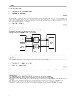
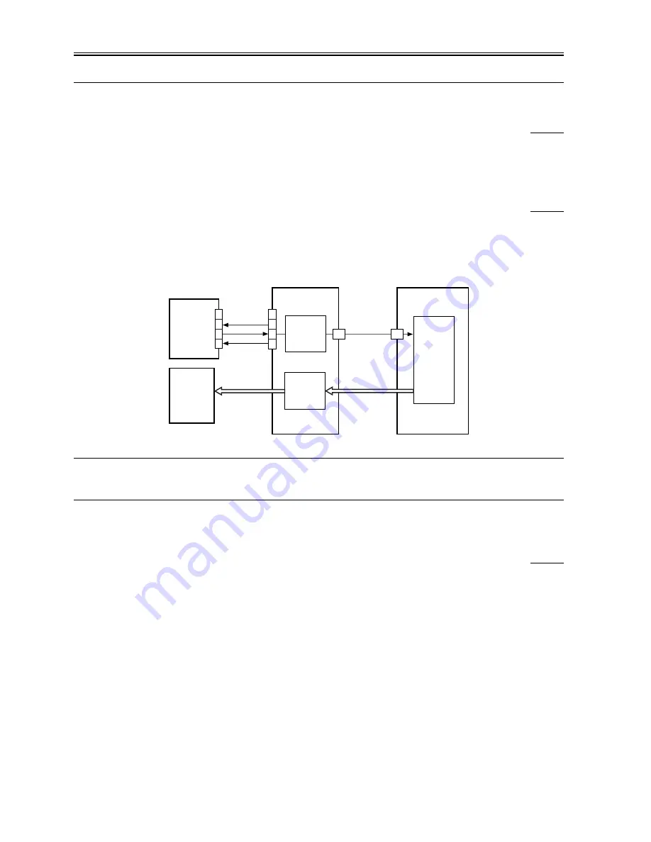
The BD signal used to synchronize the video signal in laser scanning direction is generated by the BD PCB with reference to the laser beam reflected by
the BD mirror mounted on the laser beam optical path. The CCD/AP PCB reads the image signal from the CCD, and sends it to the controller block. The
controller block, in response, executes image processing, and sends the result as a video signal to the laser driver PCB by way of the DC controller PCB
and as the laser intensity control signal to the laser unit.
6.3.1.2 Flow of the Sync Signal
0009-4069
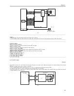
[1] BD signal (upon detection of laser light, '0').
[2] phase matching is executed with reference to the printer, and the synch signal is generated.
[3] reads the image data from the image memory in keeping with the printer sync signal.
[4] video signal
[5] converts the 2-pixel parallel signal into a signal-pixel serial signal.
[6] laser drive signal (drives the laser unit according to the video signal).
F-6-3
ERROR DODE:
E100
Issued when the BD signal is not detected within a specific period of time after the laser has been turned on.
6.3.2 Controlling the Intensity of Laser Light
6.3.2.1 Controlling the Laser Intensity
0009-4070
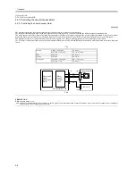
The laser driver circuit serves to drive the semi-conductor laser with reference to the laser drive signal (LD) coming from the DC controller PCB.
The laser drive circuit is associated with the following items of control:
1. laser activation control
2. laser intensity control (APC control)
3. laser intensity control to suit the drum surface potential
The various signals have the following meanings and functions:
[1] laser drive signal
[2] sample laser activation signal; for each scan, it turns on the laser for sampling of light intensity (for imaging)
[3] laser activation enable signal; after the Start key has been pressed, it goes '0'when the laser is ready for activation.
[4] laser write start signal; when paper reaches the laser write start sensor (PS28) mounted in front of the registration roller, the machine starts laser write
operation.
[5] the machine monitors the intensity of laser light upon its activation (for sampling), and feeds the appropriate value to the laser drive circuit.
[6] the machine controls the output so that the value that has been fed and the reference value from the DC controller are identical.
[7] laser intensity reference signal; it serves as the laser activation reference (determined as a result of potential control by the DC controller).
BD PCB
DC controller
PCB
BD* [1]
J2701
J116
J1015
J122
J122
J117
J101
J1015
GND
5V
VIDEO [4]
LD [6]
PHSYNC[3]
4
3
2
1
A20
1
2
3
4
Laser
drive PCB
Control block
Sync
signal
generation
[2]
Parallel/
serial
conversion
[5]
Memory
control
A21
Содержание iR5570 Series
Страница 1: ...Mar 29 2005 Service Manual iR6570 5570 Series ...
Страница 2: ......
Страница 6: ......
Страница 26: ...Contents ...
Страница 27: ...Chapter 1 Introduction ...
Страница 28: ......
Страница 30: ......
Страница 55: ...Chapter 2 Installation ...
Страница 56: ......
Страница 58: ...Contents 2 9 3 Mounting the Cassette Heater 2 34 ...
Страница 98: ......
Страница 99: ...Chapter 3 Basic Operation ...
Страница 100: ......
Страница 102: ......
Страница 110: ......
Страница 111: ...Chapter 4 Main Controller ...
Страница 112: ......
Страница 114: ......
Страница 135: ...Chapter 5 Original Exposure System ...
Страница 136: ......
Страница 181: ...Chapter 6 Laser Exposure ...
Страница 182: ......
Страница 184: ......
Страница 192: ......
Страница 193: ...Chapter 7 Image Formation ...
Страница 194: ......
Страница 198: ......
Страница 259: ...Chapter 8 Pickup Feeding System ...
Страница 260: ......
Страница 299: ...Chapter 8 8 35 F 8 51 PS36 M19 M14 Reversing flapper Outside delivery roller Point of reversal PS37 ...
Страница 349: ...Chapter 8 8 85 F 8 290 1 Feeding roller 2 Separation roller 3 Pressure lever 4 Pressure spring 1 2 A B 3 4 ...
Страница 350: ......
Страница 351: ...Chapter 9 Fixing System ...
Страница 352: ......
Страница 401: ...Chapter 10 External and Controls ...
Страница 402: ......
Страница 406: ......
Страница 448: ......
Страница 449: ...Chapter 11 MEAP ...
Страница 450: ......
Страница 452: ......
Страница 455: ...Chapter 12 Maintenance and Inspection ...
Страница 456: ......
Страница 458: ......
Страница 468: ......
Страница 469: ...Chapter 13 Standards and Adjustments ...
Страница 470: ......
Страница 505: ...Chapter 14 Correcting Faulty Images ...
Страница 506: ......
Страница 508: ......
Страница 537: ...Chapter 15 Self Diagnosis ...
Страница 538: ......
Страница 540: ......
Страница 565: ...Chapter 16 Service Mode ...
Страница 566: ......
Страница 568: ......
Страница 633: ...Chapter 17 Upgrading ...
Страница 634: ......
Страница 636: ......
Страница 641: ...Chapter 17 17 5 F 17 4 HDD Boot ROM Flash ROM System Software ...
Страница 646: ...Chapter 17 17 10 F 17 11 8 Click START F 17 12 ...
Страница 659: ...Chapter 17 17 23 F 17 32 2 Click Start F 17 33 3 When the downloading session has ended click OK ...
Страница 661: ...Chapter 17 17 25 F 17 35 2 Click Start F 17 36 3 When the downloading session has ended click OK ...
Страница 663: ...Chapter 17 17 27 F 17 38 2 Click Start F 17 39 3 When the downloading session has ended click OK ...
Страница 668: ...Chapter 17 17 32 F 17 46 2 Click Start F 17 47 3 When the downloading session has ended click OK ...
Страница 675: ...Chapter 17 17 39 F 17 59 2 Select the data to download F 17 60 3 Click Start ...
Страница 677: ...Chapter 18 Service Tools ...
Страница 678: ......
Страница 679: ...Contents Contents 18 1 Service Tools 18 1 18 1 1 List of Special Tools 18 1 18 1 2 List of Solvents Oils 18 2 ...
Страница 680: ......
Страница 683: ...Mar 29 2005 ...
Страница 684: ......


