3
1.8
REMOVAL OF EXISTING APPLIANCE
When an existing appliance is removed from a common
venting system, the common venting system is likely to be
too large for proper venting of the appliances remaining
connected to it. At the time of removal of an existing
appliance, the following steps must be followed with each
appliance remaining connected to the common venting
system placed in operation, while the other appliances
remaining connected to the common venting system are
not in operation.
•
Seal any unused openings in the common venting
system.
•
Visually inspect the venting system for proper size
and horizontal pitch and determine that there is no
blockage, restriction, leakage, corrosion or other
deficiency, which could cause an unsafe condition.
•
Insofar as is practical, close all building doors and
windows and all doors between the spaces in
which the appliances remaining connected to the
common venting system are located and other
spaces of the building. If applicable turn on the
clothes dryers and any appliances not connected
to the common venting system. Turn on any
exhaust fans, such as range hoods and bathroom
exhausts, so they will operate at maximum speed.
Do not operate a summer exhaust fan. Close
fireplace dampers.
•
Place in operation the appliance being inspected.
Follow the lighting instructions. Adjust thermostat
so that appliance operates continuously.
•
Test for spillage at the draft control device relief
opening after 5 minutes of main burner operation.
Use a cold mirror, the flame of a match, or a
candle or smoke from a cigarette.
•
After it has been determined that each appliance
remaining connected to the common venting
system properly vents when tested as outlined
above, return doors, windows, exhaust fans,
fireplace dampers and any other gas-burning
appliance to their previous condition of use.
•
Any improper operation of the common venting
system should be corrected so that the installation
conforms to the National Fuel Gas Code, ANSI
Z223.1 and/or CAN/CGA B149, Installation Codes.
When resizing any portion of the common venting
system, the common venting system should be
resized to approach the minimum size as
determined using the appropriate tables in Part 11
of the National Fuel Gas Code, ANSI Z223.1 and
/or CAN/CGA B149, Installation Codes.
Heat exchanger surfaces and vent piping should be
checked every six months for deterioration and carbon
deposits. Remove all soot or other obstructions from the
chimney and flue, which might impede draft action. Replace
any damaged or deteriorated parts of the venting system.
A qualified service technician should follow this procedure
when inspecting and cleaning the heat exchanger and vent
pipe.
1) Turn off electrical power and main manual gas shut-off
and allow appliance to cool down.
2) Remove the vent pipe at connection to heat exchanger
and check heat exchanger and vent for obstruction and
clean as necessary.
3) Remove burner from appliance and carefully clean as
required. Never brush or wipe the knitted metal fiber
surface. Use a garden hose or gently wash under the
tap. Vacuum out any deposits found in the heat
exchanger.
CAUTION
Never use a pressure washer or compressed air to clean
the burner.
4) Reinstall parts removed in steps 2 and 3. Be sure that
vent pipe has proper pitch and is properly sealed.
Replace any damaged gasket or refractory. Tighten fan
flange mounting nuts to 3 ft-lb.
5) Restore electrical power and gas supply to appliance.
6) Place appliance in operation using lighting instructions
provided.
7) Confirm proper operation of all safety devices
8) Check for gas leaks and proper vent operation.
NOTE
Experience has shown that improper installation or
system design, rather than faulty equipment, is the cause
of most operating problems
1.9
BOILER/FURNACE ROOM OPERATING
CONDITION
•
Due to low jacket losses from the appliance,
temperatures in the vicinity of the boiler room may drop
significantly; supplemental heat is required to maintain
ambient temperature at acceptable levels.
1.10 LOCATION OF UNIT
Install this appliance in a clean, dry location with adequate
service clearance.
•
Do not locate this appliance in an area where it will be
subject to freezing unless precautions are taken.
Radiant losses from the heater is minimal and should
not be relied on to keep the appliance room warm.
•
Do not locate this appliance where it may be exposed
to a corrosive atmosphere
•
The appliance should be located close to a floor drain
in an area where leakage from the appliance or
connections will not result in damage to the adjacent
area or to lower floors in the structure,
it is
recommended that a suitable drain pan, adequately
drained, be installed under the unit. Under no
circumstances is the manufacturer to be held
responsible for water damage in connection with this
unit, or any of its components.
•
If the appliance is installed above the level of the
building’s radiation system, a low water cut-off device
must be installed in the appliance outlet some distance
above the heat exchanger inlet/outlet connections.
Some local codes require the installation of a low water
cut-off on all systems
•
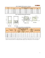
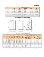
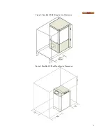
When placing the appliance be aware that a minimum
clearance of 24” must be provided at the front to allow
easy access to the heat exchanger. DynaMax HS wall
mount units do not require access through the sides
and can be placed adjacent to each other with zero
clearance. Floor mount units require access on the left
side as you face the front.
Содержание DynaMax DMH081
Страница 2: ......
Страница 12: ...7 Figure 5 DynaMax HS Wall Hung Service Clearances Figure 6 DynaMax HS Floor Mount Service Clearances...
Страница 68: ...65 PART 14 EXPLODED VIEW PARTS LIST DYNAMAX HS WALL HUNG...
Страница 69: ...66 DYNAMAX HS FLOOR MOUNT...
Страница 76: ...73 PART 15 ELECTRICAL DIAGRAMS 15 1 DM 80 299 INTERNAL WIRING DIAGRAM...
Страница 77: ...74 15 2 DM 399 800 INTERNAL WIRING DIAGRAM...
Страница 78: ...75...

