8
PART 2
AIR INLET AND VENTING
It is extremely important to follow these venting
instructions carefully. Failure to do so can cause severe
personal injury, death or substantial property damage.
2.1
GENERAL VENTING GUIDE
The DynaMax HS Wall Hung is a category IV condensing
appliance, 97% efficient unit. The DynaMax HS Floor Mount
is a category II condensing appliance, 97% efficient.
•
The
DynaMax
HS
may
be
vented
with:
manufactured prefabricated UL/ ULC listed vents of
AL29-4C or 316L stainless steel or with plastic vent
certified to UL/ ULC S636, such as, IPEX System
636 CPVC or IPEX System 636 PVC or as
permitted by local jurisdictions.
•
The DynaMax HS boiler must be vented and
supplied with combustion and ventilation air as
described in this section. Ensure that the venting
and combustion air supply complies with these
instructions.
•
Installations must be in accordance with Part 7,
“Venting of Equipment”, of the latest edition of the
National Fuel Gas Code, ANSI Z223.1 for US
installations or the latest edition of CAN/CGA
Standard B149 Installation Code for Gas Burning
Appliances and Equipment in Canada.
•
The distance of the vent terminal from adjacent
buildings, windows that open and building openings
MUST comply with the latest edition of the National
Fuel Gas Code, ANSI Z223.1 for U.S. installations
or CAN/CGA Standard B149 Installation Code for
Canadian Installations.
•
Vent connection is made directly to the flue outlet
opening on top of the unit for the wall mount unit
and at the back of the unit for floor mount. The
connection from the appliance vent to the stack
must be made as direct as possible. The first 3 feet
of vent from the appliance flue outlet must be
readily accessible for visual inspection.
•
Vent connectors serving appliances vented by
natural draft shall not be connected into any portion
of a mechanical draft system operating under
positive pressure.
•
A UL listed concentric vent/air intake kit may be
used with the DynaMax HS.
•
Horizontal runs of vent pipe shall be securely
supported (approximately every 4 feet) to prevent
sagging and maintain a minimum upward slope of
¼” per foot from the appliance to the vent terminal.
•
The weight of the venting system must not rest on
the unit. Adequate support of the venting system
must be provided in compliance with local codes
and other applicable codes.
•
All connections should be secured and sealed per
the vent manufacturer’s specifications. When a
positive vent system is disconnected for any
reason, the flue must be reassembled and resealed
according to the vent manufacturer’s instructions.
•
Do not use an existing chimney as a raceway if
another appliance or fireplace is vented through the
chimney.
•
Inspect completed vent and air supply piping
thoroughly to ensure all connections are sealed and
are in compliance with the instructions provided and
satisfy requirements of all applicable codes.
NOTE
All vent pipes must be properly assembled and supported,
and the exhaust must be pitched a minimum of 1/4 inch per
foot back to the boiler. All components used to fabricate and
assemble the vent system are to originate from the same
supplier.
Equivalent length of fittings depend on centre line radius of
the fitting. Consult published tables or the vent supplier for
accurate equivalent lengths.
Example: 30 feet of CPVC pipe + (3 x 5 feet) 90
o
(1
x 3 feet) 45
o
elbow = 48 equivalent feet of piping for
centerline radius of 1.5D, where D is the pipe diameter.
2.2
CATEGORY IV VENTING
A category IV appliance is individually vented through a
dedicated vent.
The DynaMax HS Wall Hung boilers/ water heaters shall
only be vented as a Category IV appliance.
Both Wall Hung and Floor Mount appliances shall be vented
using sealed positive vent suitable for a condensing
appliance with the following venting options:
1) Sidewall or rooftop termination where both the vent and
combustion air inlet air are in the same zone. The inlet
and vent terminals are to be installed with a minimum
12” separation distance between centerline of inlet and
centerline of exhaust. Refer to Fig. 8, 9, and 10 for
sidewall termination and Fig. 11 for rooftop termination.
2) Sidewall termination with vent and combustion air inlet
from separate zones.
3) Single Pipe thru wall or rooftop venting with combustion
air inlet from the boiler room.
NOTE
Vent Option 3 not recommended for R-2000 homes or
equivalent air tight construction.
2.2.1
Approved Venting Materials Category IV
1) PVC and CPVC (Chlorinated Polyvinyl Chloride)
Schedule 40 approved to ULC S636.
2) Manufactured prefabricated UL/ULC listed vent of AL29-
4C or 316L stainless steel. Use of 316L is limited to use in
applications where there is no possibility of contaminants
in the air such as refrigerants, chlorine etc.
3) PVC-DWV approved to comply with ANSI/ASTM D2665
(US Jurisdictions ONLY when permitted)
4) PVC Schedule 40 approved to comply with ANSI/ASTM
D1785. (US Jurisdictions ONLY when permitted)
5) CPVC Schedule 40 approved to comply with
ANSI/ASTM F441. (US Jurisdictions ONLY when
permitted)
6) Polypropylene approved to comply with ULC S636
Содержание DynaMax DMH081
Страница 2: ......
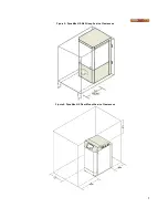
Страница 12: ...7 Figure 5 DynaMax HS Wall Hung Service Clearances Figure 6 DynaMax HS Floor Mount Service Clearances...
Страница 68: ...65 PART 14 EXPLODED VIEW PARTS LIST DYNAMAX HS WALL HUNG...
Страница 69: ...66 DYNAMAX HS FLOOR MOUNT...
Страница 76: ...73 PART 15 ELECTRICAL DIAGRAMS 15 1 DM 80 299 INTERNAL WIRING DIAGRAM...
Страница 77: ...74 15 2 DM 399 800 INTERNAL WIRING DIAGRAM...
Страница 78: ...75...

