57
For example in some cases it may be the bath tub
and in some cases it may be the clothes washer.
3) Allow the DynaMax HS to fire up and reach full fire
under
maximum
hot
water
load
demand
conditions.
4) Observe the outlet water temperature and close
the tuning valve gradually as outlet temperature
starts to drop. Allow the system to reach
equilibrium between adjustments to the tuning
valve.
5) Once the tuning valve is properly set, outlet
temperatures will never drop below
desired minimum temperature.
6) Seal stem of tuning valve with silicone to prevent
unauthorized tampering.
10.10 TEMPERATURE RISE AT FULL FIRING
RATE
1) The pump must run continuously when the burner is
firing.
2) With the pump running and the burner in the off cycle,
the inlet temperature and outlet temperature readings
on the DynaMax HS Control Panel should read
approximately the same temperatures.
3) Turn the appliance on and allow time for the
temperature to stabilize. Check the temperature rise
when the burner is firing at 100% of rated input.
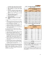
4) Compare the temperature rise on the Control Panel
with the required temperature rise at the required flow
rate on Tables 20 and 21.
5) Should adjustment be needed, proceed as follows:
If the temperature rise is too high, the water velocity is
too low. Adjust as follows:
1) Check for flow restrictions. Check for debris in strainers
2) Check diameter and equivalent length of the piping
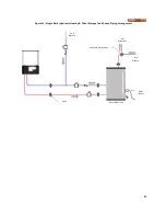
between the storage tank and hot water heater.
3) Be sure the pipes between the hot water heater and
storage tank are not more than a total of 50 equivalent
feet between supply and return lines. If maximum
equivalent length for the specified pipe diameter is
exceeded, larger diameter pipe may have to be
installed to achieve correct flow and temperature rise.
4) Be sure all valves are open between the hot water
heater and the storage tank. Ensure that all ball valves
are fully ported.
5) Check the pump to be sure it is running properly and
that the pump motor is running in the proper direction.
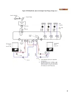
6) Common manifold piping for multiple unit installations
will require larger minimum pipe sizes and tank
circulating tapping to ensure proper flow.
The required temperature rise and the recommended pump
size are based on the heating of potable water with normal
hardness within a typical range of 7.5 to 17.0 grains per
gallon. Consult the factory when heating potable water
exceeding these specifications. Damage to the heat
exchanger as a result of scaling or corrosive water
conditions in non-warrantable.
Table 20: Temperature Rise across Heat Exchanger
(Hydronic Heating)
TEMPERATURE RISE ACROSS HEAT
EXCHANGER
MODEL
[BTU/hr]
30
o
F (16.7
o
C)
35
o
F (19.4
o
F)
USGPM
∆
P-Ft.
USGPM
∆
P-Ft.
80,000
5.0
8.2
4.3
6.2
100,000
6.3
12.3
5.4
9.4
150,000
9.5
10.4
8.1
7.8
199,000
12.6
7.2
10.8
5.8
250,000
15.8
11.5
13.5
8.7
299,000
18.9
9.3
16.2
7.0
399,000
25.2
8.4
21.6
6.3
500,000
31.5
9.2
27.0
6.9
600,000
38.8
17.5
32.0
11.8
700,000
45.3
18.2
40.0
14.4
800,000
51.8
23.5
43.0
16.0
Table 21: Temperature Rise across Heat Exchanger
(DHW)
TEMPERATURE RISE ACROSS HEAT
EXCHANGER
MODEL
[BTU/hr]
20
O
F (11.1
o
C)
USGPM
∆
P-Ft.
80,000
7.5
11.5
100,000
9.4
26.9
150,000
14.0
27.8
199,000
19.2
25.9
250,000
23.5
28.3
299,000
28.8
25.8
399,000
38.4
23.9
500,000
48.6
29.4
600,000
57.6
34.2
700,000
70.4
40.0
800,000
77.6
43.2
CAUTION
Temperature rise cannot be adjusted when the burner is
firing at less than 100% of input rate.
CAUTION
Adequate care MUST be taken to prevent potential scald
injury when storing water at 140°F (60°C) and hotte r.
WARNING
Should overheating occur or the gas supply fail to shut off,
do not turn off or disconnect the electrical supply to the
pump, instead, shut off the gas supply at a location external
to the appliance
Содержание DynaMax DMH081
Страница 2: ......
Страница 12: ...7 Figure 5 DynaMax HS Wall Hung Service Clearances Figure 6 DynaMax HS Floor Mount Service Clearances...
Страница 68: ...65 PART 14 EXPLODED VIEW PARTS LIST DYNAMAX HS WALL HUNG...
Страница 69: ...66 DYNAMAX HS FLOOR MOUNT...
Страница 76: ...73 PART 15 ELECTRICAL DIAGRAMS 15 1 DM 80 299 INTERNAL WIRING DIAGRAM...
Страница 77: ...74 15 2 DM 399 800 INTERNAL WIRING DIAGRAM...
Страница 78: ...75...

