13
PART 3
GAS CONNECTION
Verify that the appliance is supplied with the type of gas
specified on the rating plate. Consult factory for installations
at high altitude.
3.1
GAS CONNECTION
•
Safe operation of unit requires properly sized gas supply
piping. See gas line sizing data.
•
Gas pipe size may be larger than appliance connection.
•
Installation of a union at the appliance gas line
connection is required for ease of service and removal
of the gas train.
•
Install a manual main gas shutoff valve, outside of the
appliance as required by local codes.
•
A trap (drip leg) MUST be provided in the inlet gas
connection to the appliance.
•
Optional gas controls may require routing of bleeds and
vents to the atmosphere, outside the building when
required by local codes.
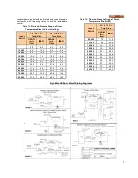
Table 8: Recommended Gas Pipe Size
Single Appliance Installation
(For distance from natural gas meter or propane second
stage regulator)
Input
0-100 FT
101-200 FT
201-300 FT
Btu/Hr,
x1000
NAT.
L.P.
NAT.
L.P.
NAT.
L.P.
80
¾”
½”
¾”
½”
1”
¾”
100
¾”
½”
1”
¾“
1”
¾”
150
1”
¾”
1 ¼”
1“
1 ¼”
1”
200
1”
¾”
1 ¼”
1”
1 ¼”
1”
250
1 ¼”
1”
1 ¼”
1”
1 ½”
1 ¼”
299
1 ¼“
1“
1 ½”
1 ¼“
1 ½“
1 ¼“
399
1 ¼“
1“
1 ½“
1 ¼“
2“
1 ½“
500
1 ½“
1 ¼“
2“
1 ½“
2“
1 ½“
600
1 ½“
1 ¼“
2“
1 ½“
2“
1 ½“
700
2 “
1 ½“
3“
2 ½“
3“
2 ½ “
800
2 “
1 ½“
3“
2 ½“
3“
2 ½ “
3.2
GAS PIPING
All gas connections must be made with pipe joint compound
resistant to the action of liquefied petroleum and natural gas.
All piping must comply with local codes and ordinances.
3.3
INSTALL PIPING
•
The gas line must be sufficient to handle the total
installed capacity. Verify pipe size with your gas
supplier.
•
Use approved piping as per code.
•
Install a manual main gas shutoff valve at the appliance
gas inlet, outside of the appliance and before the gas
valve.
•
Run pipe to the Appliance gas inlet.
•
Install a sediment trap in the supply line to the Appliance
gas inlet.
•
Apply a moderate amount of good quality pipe
compound.
•
For LP gas, consult your LP gas supplier for expert
installation.
The appliance and its individual gas shut-off valve must be
disconnected from the supply piping when pressure testing
the gas supply piping at pressures above ½ PSI
Table 9: Gas Pressures at Inlet to Appliance
PROPANE
NATURAL GAS
Minimum (inches W.C.)
11
3
Maximum (inches W.C.)
11
14
The gas supply line must be of adequate size to prevent
undue pressure drop and must never be smaller than the
size of the connection on the appliance. Sizing based on
Table 8 is recommended, depending on model.
Before operating the appliance, the complete gas train and
all connections must be tested using soap solution.
Verify that the appliance is supplied with the type of gas
specified on the rating plate. Heating values of local natural
gas are to be between 950 and 1010 Btu/ft
3
. Consult factory
if heating values are outside this range or if a gas with a
mixture of constituents is being used.
3.4
CHECKING GAS SUPPLY PRESSURE
•
Turn main power switch to “OFF” position.
•
Shut off gas supply at the manual gas cock in the gas
piping to the appliance. If fuel supply is LP gas, shut off
gas supply at the tank.
•
DM80 – 399: Loosen the slotted screw from the gas
pressure test port on the gas valve. Connect manometer
or magnahelic gauge to test port. Range of scale should
be 0 to 14 inch W.C. or greater to check inlet pressure.
•
DM500 – 800: Remove the 1/8" hex plug from the gas
pressure test port located upstream of gas valve. Install
a pressure tapping suitable to connect to a manometer
or magnahelic gauge. Range of scale should be 0 to 14
inch W.C. or greater to check inlet pressure.
•
Turn on gas supply at field installed manual gas cock;
turn on LP gas at tank if required.
•
Turn power switch to “ON” position.
•
Initialize call for heat.
•
Observe the gas supply pressure as the burner fires at
100% of rated input. Supply pressure is to remain
stable.
•
Ensure inlet pressure is within specified range as
specified in Table 9.
•
If gas pressure is out of range, contact the gas utility,
gas supplier, qualified installer or service agency to
determine necessary steps to provide proper gas
pressure to the control.
•
If gas supply pressure is within normal range, proceed
to remove gas manometer and tighten slotted screw on
gas valve (DM80 – 399) or replace pressure tap fittings
in the gas piping to the appliance (DM500 – 800). Turn
power switch to “OFF” position.
•
Turn on gas supply at the manual valve; turn on LP gas
at tank if required.
•
Turn power switch to “ON” position.
•
Adjust set point to the desired water temperature.
•
Check appliance performance by cycling the system
while you observe burner response. The burner should
ignite promptly. Flame profile should be stable, see
section 11.2, Visually Check Main Burner Flames. Turn
system off and allow burner to cool, then cycle burner
again
to
ensure
proper
ignition
and
flame
characteristics.
Содержание DynaMax DMH081
Страница 2: ......
Страница 12: ...7 Figure 5 DynaMax HS Wall Hung Service Clearances Figure 6 DynaMax HS Floor Mount Service Clearances...
Страница 68: ...65 PART 14 EXPLODED VIEW PARTS LIST DYNAMAX HS WALL HUNG...
Страница 69: ...66 DYNAMAX HS FLOOR MOUNT...
Страница 76: ...73 PART 15 ELECTRICAL DIAGRAMS 15 1 DM 80 299 INTERNAL WIRING DIAGRAM...
Страница 77: ...74 15 2 DM 399 800 INTERNAL WIRING DIAGRAM...
Страница 78: ...75...

