59
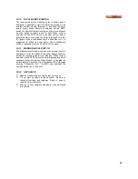
10.12 LOCAL/REMOTE SWITCH
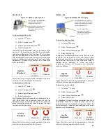
The local remote switch mounted on the terminal board is
designed to generate a call for heat either relying on an
external contact closure (Remote) or enabling the boiler
locally (local). When Remote is selected via the SPDT
switch the Remote Operator contacts on the terminal board
must be closed to initiate a call for heat. When Local is
selected via the SPDT switch a constant call for heat is
generated which will enable the boiler to proceed to a trial
for ignition. When troubleshooting the DynaMax HS it is
suggested to switch to Local mode. The Local/Remote
switch is independent of the 4-20mA/2-10Vdc signal.
10.13 MODBUS/LOCAL SWITCH
The Modbus/Local Switch mounted on the terminal board is
designed to relay the signal to the boiler display (local) or
accept an incoming signal from Modbus. When local is
selected via the DPDT switch the boiler display presents all
necessary boiler information. When Modbus is toggled the
boiler display will continue to be illuminated with a message
showing “Connection lost”. The BMS now overrides the
communication link to the boiler.
10.14 APPLIANCE
∗
Remove manometers and tighten test port screws.
∗
Fill out start up report for each heater. Be sure to
record all settings and readings. Retain a copy of
report for future reference.
∗
Start up is now complete and heater may be placed
into service.
Содержание DynaMax DMH081
Страница 2: ......
Страница 12: ...7 Figure 5 DynaMax HS Wall Hung Service Clearances Figure 6 DynaMax HS Floor Mount Service Clearances...
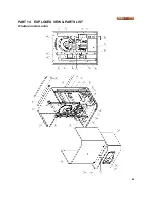
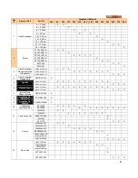
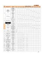
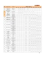
Страница 68: ...65 PART 14 EXPLODED VIEW PARTS LIST DYNAMAX HS WALL HUNG...
Страница 69: ...66 DYNAMAX HS FLOOR MOUNT...
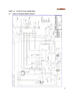
Страница 76: ...73 PART 15 ELECTRICAL DIAGRAMS 15 1 DM 80 299 INTERNAL WIRING DIAGRAM...
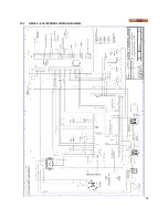
Страница 77: ...74 15 2 DM 399 800 INTERNAL WIRING DIAGRAM...
Страница 78: ...75...

