15
This appliance uses a single cylindrical burner installed
horizontally into the cavity located in the center of the heat
exchanger. A unique burner is used for each one of the
DynaMax HS models.
Burners may NOT be interchanged between different Btu/hr
input models. The burner consists of a round mounting
flange welded to a ported stainless steel mixing tube. This
stainless steel tube is covered with a close fitting, knitted
stainless steel metal fiber alloy material that forms the burner
outer surface. The burner is setup to operate in blue mode
and infrared operating condition should be avoided. Infrared
operation will occur only if air to gas adjustments is incorrect.
If infrared operation is noted the cause must be corrected.
The burner should be removed for inspection and cleaning
on an annual basis. An appliance installed in a dust or dirt
contaminated environment will require inspection and
cleaning on a more frequent schedule. The fan assisted
combustion process may force airborne dust and dirt
contaminants, contained in the combustion air, into the
burner.
With
sustained
operation,
non-combustible
contaminants may reduce burner surface area, reduce
burner input or cause non-warrantable damage to the
burner.
Airborne contaminants such as dust, dirt, concrete dust or
dry wall dust can be drawn into the burner with the
combustion air and block the burner surface area. DO NOT
operate this appliance during construction.
The spark igniter and flame sensor are removable from the
combustion chamber mounting door without removing the
burner assembly.
Never use an open flame (match, lighter, etc.) to check
gas connections.
Regulated Gas Supply Pressures for DynaMax HS
Boilers & Water Heaters
A stable gas supply pressure is important to avoid rough
starts with machines like the DynaMax HS which use a 1 to
1 ratio control valve for internal gas pressure regulation.
Camus requires that all DynaMax HS models be supplied
with no more than 14” w.c. supply pressure. This means that
lockup pressure must not exceed 14” w.c.
A suitable lockup regulator with internal or external relief will
not exceed running pressure by more than 20%.
When required a final stage gas regulator is to be located as
close as possible but no more than 10 feet from the
appliance.
It is paramount that maximum lockup pressure be confirmed
before any attempt is made to start up the appliance.
Operating the DynaMax HS at lockup pressures exceeding
14” w.c. could lead to delayed ignitions and damage to the
appliance.
PART 4
WATER CONNECTION
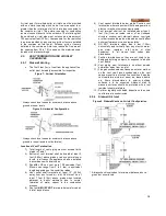
•
Check all applicable local heating, plumbing and
building safety codes before proceeding.
•
If the appliance is installed above radiation level it must
be provided with a low water cut-off device at the time of
appliance installation (available from Camus). Some
local codes require the installation of a low water cut-off
on all systems.
•
Before connecting DynaMax HS to piping in a closed
loop system, flush system thoroughly and refill with
clean water and add chemical treatment to bring into
balance.
•
Follow the chemical suppliers instructions. A regular
maintenance schedule will ensure that acceptable water
quality is maintained, typically a Langlier/ Reznor index
will provide this information.
•
Strainers are recommended to be installed into the
system to prevent foreign objects from entering the heat
exchanger.
•
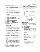
A pressure relief valve is supplied with each DynaMax
HS. The relief valve must be mounted in a vertical
position and piped to the floor in a manner acceptable to
the enforcing authority.
•
Be sure to provide unions and gate valves at inlet and
outlet to the appliance so that it can be easily isolated
for service.
•
On combination heaters a flow setter valve at the
appliance outlet facilitates setting of the desired outlet
temperature at high fire. Refer to Section 10.9 Domestic
Hot Water with Plate Heat Exchanger for more details
•
This appliance is a low mass stainless steel tube design
which provides for instant heat transfer. All appliances
are supplied with an internal suitable specific pump
mounted in place. When replacing the pump, replace
with one of equal or better-performance.
•
An air vent is supplied on the heat exchanger header to
eliminate trapped air. Install venting devices at high
points in the system as well to eliminate trapped air in
the piping.
•
Use suitable pipe hangers or floor stands to support the
weight of all water and gas piping.
•
The DynaMax HS must be installed so that the gas
ignition system components are protected from water
(dripping, spraying, rain, etc.) during appliance
operation and service (circulator replacement, control
replacement, etc.)
4.1
FREEZE PROTECTION OUTDOOR
INSTALLATION
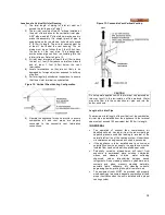
•
Appliance installations are not recommended outdoors
or in areas where danger of freezing exists unless
precautions are taken. Maintaining a mixture of 70%
water and 30% propylene glycol is the preferred method
of freeze protection in hydronic systems. DO NOT
exceed a mixture of 50/50. This mixture will protect the
appliance to approximately -35ºF (-37ºC). Follow the
chemical suppliers directions.
•
For outdoor installations a snow screen should be
installed to prevent snow and ice accumulation around
the appliance. Regular inspections should be made to
ensure that air inlet and vent are free of snow and ice.
Always consider the use of a shelter such as a garden
shed in lieu of direct exposure of the appliance to the
elements. The additional protection afforded by the
Содержание DynaMax DMH081
Страница 2: ......
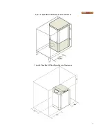
Страница 12: ...7 Figure 5 DynaMax HS Wall Hung Service Clearances Figure 6 DynaMax HS Floor Mount Service Clearances...
Страница 68: ...65 PART 14 EXPLODED VIEW PARTS LIST DYNAMAX HS WALL HUNG...
Страница 69: ...66 DYNAMAX HS FLOOR MOUNT...
Страница 76: ...73 PART 15 ELECTRICAL DIAGRAMS 15 1 DM 80 299 INTERNAL WIRING DIAGRAM...
Страница 77: ...74 15 2 DM 399 800 INTERNAL WIRING DIAGRAM...
Страница 78: ...75...

