17
condominiums, apartments and motels and typically used in
conjunction with tempering valves to achieve temperature
control.
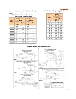
Table 11: Flow and Pressure Drop at a Given
Temperature Rise (Hydronic Heating)
Input,
Btu/Hr
30 °F (16.7 °C)
35 °F (19.4 °C)
Temp Rise
Temp Rise
USGPM
(min.
flow)
∆∆∆∆
P Ft.
USGPM.
(min.
flow)
∆∆∆∆
P Ft.
5.0
8.2
4.3
6.2
100,000
6.3
12.3
5.4
9.4
150,000
9.5
10.4
8.1
7.8
199,000
12.6
7.2
10.8
5.8
250,000
15.8
11.5
13.5
8.7
299,000
18.9
9.3
16.2
7.0
399,000
25.2
8.4
21.6
6.3
500,000
31.5
9.2
27.0
6.9
600,000
38.8
17.5
32.0
11.8
700,000
45.3
18.2
40.0
14.4
800,000
51.8
23.5
43.0
16.0
Table 12: Flow and Pressure Drop at a Given
Temperature Rise (DHW)
Input,
Btu/Hr
20 °F (11.1 °C)
Temp Rise
USGPM
(min.
flow)
∆∆∆∆
P Ft.
80,000
7.5
11.5
100,000
9.4
26.9
150,000
14.0
27.8
199,000
19.2
25.9
250,000
23.5
28.3
299,000
28.8
25.8
399,000
38.4
23.9
500,000
48.6
29.4
600,000
57.6
34.2
700,000
70.4
40.0
800,000
77.6
43.2
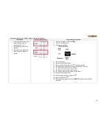
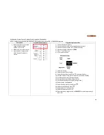
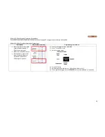
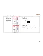
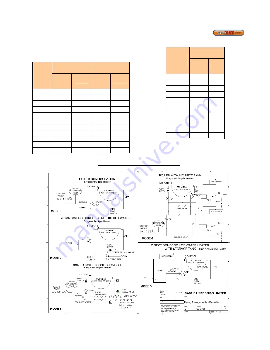
DynaMax HS Floor Mount Piping Diagrams
Содержание DynaMax DMH081
Страница 2: ......
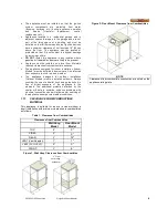
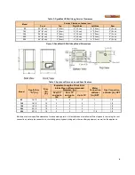
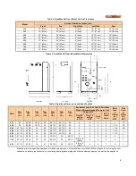
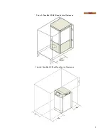
Страница 12: ...7 Figure 5 DynaMax HS Wall Hung Service Clearances Figure 6 DynaMax HS Floor Mount Service Clearances...
Страница 68: ...65 PART 14 EXPLODED VIEW PARTS LIST DYNAMAX HS WALL HUNG...
Страница 69: ...66 DYNAMAX HS FLOOR MOUNT...
Страница 76: ...73 PART 15 ELECTRICAL DIAGRAMS 15 1 DM 80 299 INTERNAL WIRING DIAGRAM...
Страница 77: ...74 15 2 DM 399 800 INTERNAL WIRING DIAGRAM...
Страница 78: ...75...

