12
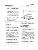
Location of a Vertical Air Inlet Opening
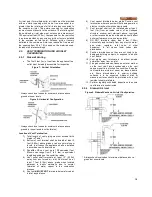
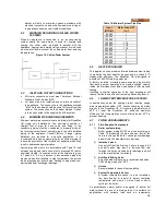
1) The total length of piping for inlet air must not
exceed the limits given in Table 7.
2) The air inlet consists of two 90
o
elbows installed at
the point of termination for the vertical air inlet pipe.
A 90
o
elbow and a 90
o
street elbow may be used to
make this assembly. If a straight piece of pipe is
used between the two elbows, it should not exceed
6” (0.15m) in length. The air inlet opening must be
at least 1 foot below the vent opening. The air
piping must be no further than 2 feet (0.6m) from
the center of the vent pipe. This arrangement
avoids exhaust gases from re-circulating into the
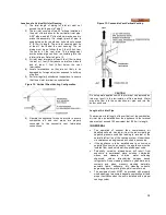
inlet air stream. Refer to Figure 12.
3) Air inlet must terminate at least 3 feet (1.0m) above
the roof or 1 foot (0.3m) above normal snow levels
and at least 1 foot (0.3m) below the vent
termination.
4) Locate terminations so they are not likely to be
damaged by foreign objects or exposed to build-up
of debris.
5) Perform regularly scheduled inspections to ensure
that the air inlet terminal is unobstructed.
Figure 12: Vertical Direct Venting Configuration
6) Operate the appliance for one heat cycle to ensure
combustion air and vent pipes are properly
connected to the concentric vent termination
connections.
Figure 13: Concentric Vent Vertical Venting
CAUTION
Do not operate appliance with the terminal cap removed as
this may result in the recirculation of flue products. Water
may also flow into the combustion air pipe and into the
burner enclosure.
Length of Air Inlet Pipe
The maximum total length of the vertical roof top combustion
air inlet pipe as installed from the appliance to the terminal
cap must not exceed 100 equivalent feet (30.5m) in length.
IN GENERAL
•
The operation of exhaust fans, compressors, air
handling units etc. can rob air from the room, creating a
negative pressure condition leading to reversal of the
natural draft action of the venting system. Under these
circumstances an engineered air supply is necessary.
•
If the appliance is to be installed near a corrosive or
potentially corrosive air supply, the appliance must be
isolated from it and outside air supplied as per code.
•
Potentially corrosive atmospheres will result from
exposure to permanent wave solution, chlorinated
waxes
and
cleaners,
chlorine,
water
softening
chemicals,
carbon
tetrachloride,
halogen
based
refrigerants, Freon cleaning solvents, hydrochloric acid,
cements and glues, masonry washing materials,
antistatic fabric softeners, dry cleaning solvents,
degreasing liquids, printing inks, paint removers, etc.
•
The equipment room MUST be provided with properly
sized openings to assure adequate combustion air and
proper ventilation when the unit is installed with a proper
venting system.
Содержание DynaMax DMH081
Страница 2: ......
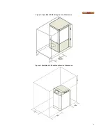
Страница 12: ...7 Figure 5 DynaMax HS Wall Hung Service Clearances Figure 6 DynaMax HS Floor Mount Service Clearances...
Страница 68: ...65 PART 14 EXPLODED VIEW PARTS LIST DYNAMAX HS WALL HUNG...
Страница 69: ...66 DYNAMAX HS FLOOR MOUNT...
Страница 76: ...73 PART 15 ELECTRICAL DIAGRAMS 15 1 DM 80 299 INTERNAL WIRING DIAGRAM...
Страница 77: ...74 15 2 DM 399 800 INTERNAL WIRING DIAGRAM...
Страница 78: ...75...

