61
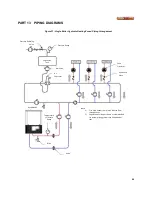
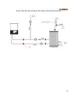
Figure 32: Single Combination Boiler Zoned Piping Arrangement
Pressure Reducing
Valve
Pressure Gauge
Ball Valve
Air
Separator
Expansion
Tank
Zone
Circulator
Flow Check
Valve
DynaMax HS
Boiler
Temperature
/ Pressure
Gauge
Drain
Union
Anti-scald Mixing Valve
Note:
1)
Size main header to minimize induced flow
through zones
2)
Separate boiler loop as shown is recommended
for system piping greater than 50 equivalent
feet.
Содержание DynaMax DMH081
Страница 2: ......
Страница 12: ...7 Figure 5 DynaMax HS Wall Hung Service Clearances Figure 6 DynaMax HS Floor Mount Service Clearances...
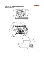
Страница 68: ...65 PART 14 EXPLODED VIEW PARTS LIST DYNAMAX HS WALL HUNG...
Страница 69: ...66 DYNAMAX HS FLOOR MOUNT...
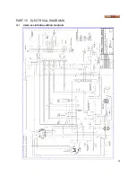
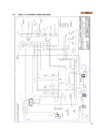
Страница 76: ...73 PART 15 ELECTRICAL DIAGRAMS 15 1 DM 80 299 INTERNAL WIRING DIAGRAM...
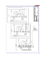
Страница 77: ...74 15 2 DM 399 800 INTERNAL WIRING DIAGRAM...
Страница 78: ...75...

