77
15.5
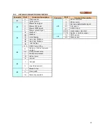
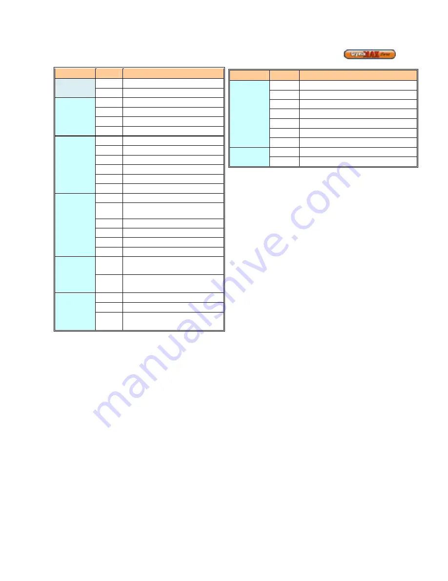
DETAILED CONNECTOR DESCRIPTION
Connector
Pin #
Connector Description
J1
2
Flame sensor
3
Igniter ground
J2
1
Blower tach signal
2
Blower Vdc power
3
Blower PWM signal
4
Blower ground signal
J3
A1
B1
Modbus -
C1
+Vdc Display
A2
Lead Lag,
B2
Lead Lag, Modbus -
C2
-Vdc Display
J4
2, 3
DHW Pump, 1/6hp
4
24Vac or 115Vac for pump
contact
5,6
3-way diverter valve
7
Boiler pump contact
10
24Vac return
12
Ground
J5
1
Interlock
2
Gas Valve contact
J6
1
Blocked Flue
2
Flow switch
7,8
Alarm, dry contacts
Connector
Pin #
Connector Description
J8
1
24Vac for SOLA
2
24Vac return
3
Remote enable/disable signal
4,5
Inlet sensor
6,7
4-20mA Input
8,9,10
Outlet sensor, high limit
11, 12
System or Outdoor sensor
J9
1,2
DHW sensor
4,5
Stack sensor
Содержание DynaMax DMH081
Страница 2: ......
Страница 12: ...7 Figure 5 DynaMax HS Wall Hung Service Clearances Figure 6 DynaMax HS Floor Mount Service Clearances...
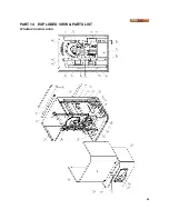
Страница 68: ...65 PART 14 EXPLODED VIEW PARTS LIST DYNAMAX HS WALL HUNG...
Страница 69: ...66 DYNAMAX HS FLOOR MOUNT...
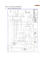
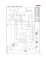
Страница 76: ...73 PART 15 ELECTRICAL DIAGRAMS 15 1 DM 80 299 INTERNAL WIRING DIAGRAM...
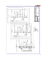
Страница 77: ...74 15 2 DM 399 800 INTERNAL WIRING DIAGRAM...
Страница 78: ...75...

