


Section 7. Installation
159
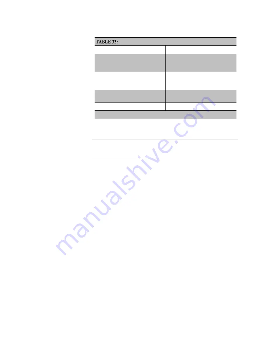
Common Configuration Actions and Tools
Action
Tools to Use
1
Updating the operating system
DevConfig
(p. 148)
software,
Program
Send
(p. 596),
memory card
(p. 86),
mass
storage device
Access a register
DevConfig
,
PakBus Graph
, CRBasic
program,
'Include' file
(p. 154),
Default.CR6 file
(p. 154).
Set the CR6 clock
DevConfig
,
PC200W
,
PC400
,
LoggerNet
Save / restore configuration
DevConfig
1
Tools are listed in order of preference.
7.5.2.1 On-Board Wi-Fi
Related Topics:
•
On-Board Wi-Fi — Setup
(p. 159)
•
On-Board Wi-Fi — Operation
(p. 516)
You can connect to your CR6-WIFI with your mobile device, PC, or network in
one of the following ways:
•
Set up the CR6-WIFI to create its own network as an access point. Your
mobile device or PC then connects to that network. This is the method
used when linking the CR6-WIFI to the NL240 wireless link.
•
Set up the CR6-WIFI and your mobile device or PC to join a network
hosted by a wireless-access point, such as a wireless router.
The CR6-WIFI cannot be used as a wireless router outside of a PakBus network.
Go to the following video tutorials for more help:
•
CR
6-
WIFI tutorial: https://www.campbellsci.com/videos?video=86
•
LoggerLink
video: https://www.campbellsci.com/videos?vi
deo=7
The following written procedures step you through setting up Wi-Fi comms either
way.
Содержание CR6 Series
Страница 2: ......
Страница 4: ......
Страница 6: ......
Страница 32: ......
Страница 36: ......
Страница 38: ......
Страница 76: ...Section 5 Overview 76 FIGURE 20 Half Bridge Wiring Example Wind Vane Potentiometer ...
Страница 80: ...Section 5 Overview 80 FIGURE 23 Pulse Input Wiring Example Anemometer ...
Страница 136: ......
Страница 251: ...Section 7 Installation 251 FIGURE 46 Running Average Frequency Response FIGURE 47 Running Average Signal Attenuation ...
Страница 454: ...Section 8 Operation 454 FIGURE 104 Narrow Sweep High Noise ...
Страница 459: ...Section 8 Operation 459 FIGURE 106 Vibrating Wire Sensor Calibration Report ...
Страница 535: ...Section 8 Operation 535 8 11 2 Data Display FIGURE 121 CR1000KD Displaying Data ...
Страница 537: ...Section 8 Operation 537 FIGURE 123 CR1000KD Real Time Custom ...
Страница 538: ...Section 8 Operation 538 8 11 2 3 Final Storage Data FIGURE 124 CR1000KD Final Storage Data ...
Страница 539: ...Section 8 Operation 539 8 11 3 Run Stop Program FIGURE 125 CR1000KD Run Stop Program ...
Страница 541: ...Section 8 Operation 541 FIGURE 127 CR1000KD File Edit ...
Страница 542: ...Section 8 Operation 542 8 11 5 PCCard Memory Card Management FIGURE 128 CR1000KD PCCard Memory Card Management ...
Страница 546: ......
Страница 549: ...Section 9 Maintenance Details 549 FIGURE 133 Separate Back Shell from Module FIGURE 134 Disconnect Battery Connector ...
Страница 552: ......
Страница 610: ...Section 11 Glossary 610 FIGURE 137 Relationships of Accuracy Precision and Resolution ...
Страница 612: ......
Страница 648: ......
Страница 650: ......
Страница 688: ......
Страница 689: ......


