164
165
c. Use the controlled position lever (38) to raise
the implement at the end of each pass.
•
floating mode
a. Move the controlled position lever (38, fig.
6.7) the controlled draft lever (39) all the way
forward.
b. Lower and lift the attachment at the beginning
and end of each pass using the controlled posi-
tion lever (38).
•
Combined controlled position and
draft mode
a. Insert the attachment into the ground and set
the required depth as described in the section
on “Controlled draft” above.
b. When the attachment has stabilized at the re-
quired depth, move the controlled position lever
(38, fig. 6.7) back until the links tend to lift.
NOTE
Under these conditions, the power lift is in
controlled position mode but if the atta-
chment encounters less resistance from the
soil, it will not be excessively buried in the
ground.
c. Lower of the lift the attachment at the begin-
ning and end of each pass using the controlled
position lever (38).
•
Regulation link lower rate
Lever (38, fig. 6.7) regulates link lower rate.
•
On-road driving with attachment coupled
a. Turn link lower regulation lever (41, fig. 6.7)
all the way anticlockwise.
c. Sollevare l’attrezzo alla fine di ogni passata
mediante la leva controllo posizione (38).
•
funzionamento flottante
a. Portare la leva controllo posizione (38, fig.
6.7) e la leva controllo sforzo (39) completa-
mente in avanti
b. Abbassare e sollevare l’attrezzo all’inizio ed
alla fine di ogni passata mediante la leva con-
trollo posizione (38).
•
Controllo misto di posizione e sforzo
a. Interrare l’attrezzo e stabilire la profondità di
lavoro desiderata procedendo come descritto
nel par. “Sforzo controllato”.
b. Quando l’attrezzo si è stabilizzato alla profon-
dità desiderata, spostare la leva controllo posi-
zione (38, fig. 6.7) all’indietro fino a che i bracci
del sollevatore tendano a sollevarsi.
NOTA
In questa condizione, il sollevatore funziona
a sforzo controllato, ma nel caso che l’at-
trezzo incontri zone di terreno di minor resi-
stenza, evita un eccessivo interramento del-
l’attrezzo stesso.
c. Abbassare e sollevare l’attrezzo all’inizio ed
alla fine di ogni passata agendo sulla leva con-
trollo posizione (38).
•
Regolazione velocità di discesa bracci
La levetta (41, fig. 6.7) consente di regolare la
velocità di discesa dei bracci.
•
Trasferimento su strada con attrezzo
collegato
a. Ruotare la levetta regolazione velocità di di-
scesa bracci (41, fig. 6.7) completamente in
senso antiorario.
G
B
I
114
Содержание VALIANT 400
Страница 2: ......
Страница 87: ...87 4 45...
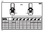
Страница 174: ...174 122 14 1 RS L C L C mm...
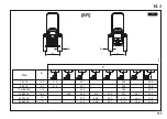
Страница 175: ...175 123 RS L C L C in 14 2...
Страница 200: ...200 027106 D E 6 5 4 A B 2 C 3 1 B B D C A A E 17 136...
Страница 221: ...221...
Страница 242: ...242...
Страница 243: ......


