
Ex p Control Unit
SIEMENS Set
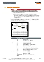
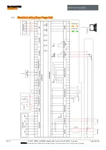
Electrical connections
Rev. 0
01-37A2-7D0004_SIEMENS_Manual_Exp-Control-Unit_20220216_0_en.docx
Page 37 of 80
Disclaimer: We reserve the right to make technical changes. Changes, errors and printing errors do not justify claims for damages.
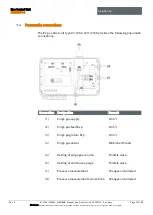
6.2.1.2
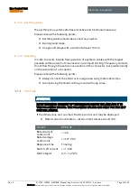
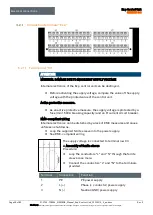
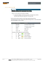
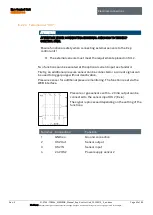
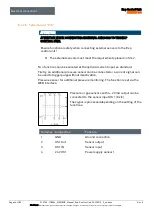
Terminal row “X5”
The Ex p control unit has one floating
changeover contact K3 and one
floating changeover contact K4 for
signaling and processing signals. The
associated switching function can be
set in the Ex p control unit via the WEB
interface and is freely programmable.
Terminal
Connection
Function
1
K3 – COM
Foot contact
2
K3 – NO
Normally open contact
3
K3 – NC
Normally closed contact
4 / 5
PE
6
K4 – COM
Foot contact
7
K4 – NO
Normally open contact
8
K4 – NC
Normally closed contact
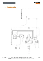
6.2.1.3
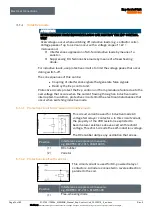
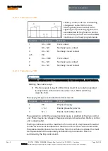
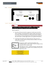
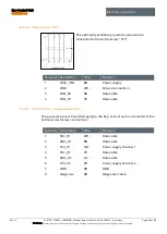
Terminal row “X8“
ATTENTION
MATERIAL DAMAGE DUE TO OVERCURRENT IN THE CONTROL ELECTRONICS.
Welding the enable relays.
The Ex p enable (relay K1, X8 terminal 2 and 3) can only be operated
in conjunction with a mains fuse (max. 5 A, 1,500 A switching
capacity, fast).
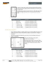
The supply voltage is connected to terminal row X8.
Terminal
Connection
Function
1
PE
PE power supply
2
L´ (+)
Enable phase Ex p device
3
N´ (-)
Enable neutral Ex p device
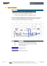
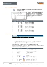
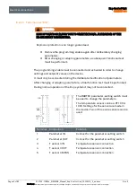
The application within the pressurized enclosure is enabled by the Ex p control
unit. There may be no voltage in the pressurized enclosure when the Ex p control
unit is deactivated.
The Ex p enable can switch a maximum of one circuit of one phase with neutral
conductor and can be loaded with a maximum of 5 A. If the current load within
the pressurized enclosure has more than 5 A or more than one phase, this must
be implemented with a separately certified Ex d preconductor which is
controlled by the Ex p control unit.
Содержание Ex p Control Unit APEX
Страница 1: ...Manual Ex p Control Unit APEX Set SIEMENS ...


