Ex p Control Unit
SIEMENS Set
Electrical connections
Rev. 0
01-37A2-7D0004_SIEMENS_Manual_Exp-Control-Unit_20220216_0_en.docx
Page 41 of 80
Disclaimer: We reserve the right to make technical changes. Changes, errors and printing errors do not justify claims for damages.
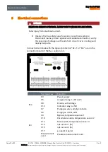
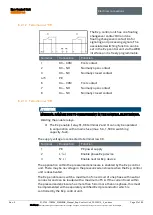
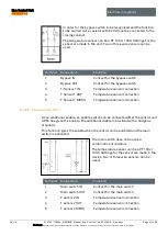
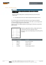
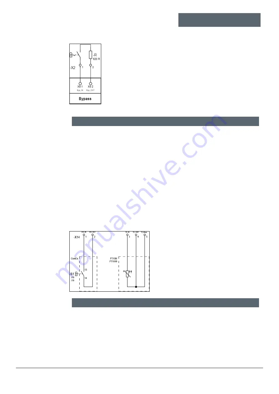
In order for the bypass switch to be recognized and the function
to be carried out, a resistor with 620
Ω
must be connected to the
closing contact.
The temperature sensor can be a PT 100 or 1000. Settings for the
sensor are made in the unit. Two or three wire sensors can be
used.
Terminal
Connection
Function
1
Bypass IN
Contact for the bypass switch
2
Bypass OUT
Contact for the bypass switch
3
T-Sensor 1 IN
Temperature sensor connection
4
T Sensor 1 OUT
Temperature sensor connection
5
T Sensor 1 MESS
Temperature sensor connection
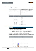
6.2.2.2
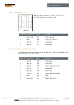
Terminal row “X14“
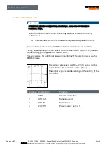
As an additional enable, an enable switch can be connected after the control unit
APEX has given the enable. The additional enable is provided with a bridge as
standard.
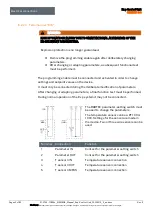
This function gives the enable when the control unit is enabled and the main
switch is activated.
The main switch does not require a
combination of resistors.
The temperature sensor can be a PT 100 or
1000. Settings for the sensor are made in the
device. Two or three wire sensors can be
used.
Terminal
Connection
Function
1
Main switch IN
Contact for the main switch
2
Main switch OUT
Contact for the main switch
3
T sensor 2 IN
Temperature sensor connection
4
T sensor 2 OUT
Temperature sensor connection
5
T sensor 2 MESS
Temperature sensor connection
Содержание Ex p Control Unit APEX
Страница 1: ...Manual Ex p Control Unit APEX Set SIEMENS ...

