Installation
Ex p Control Unit
SIEMENS Set
Page 26 of 80
01-37A2-7D0004_SIEMENS_Manual_Exp-Control-Unit_20220216_0_en.docx
Rev. 0
Disclaimer: We reserve the right to make technical changes. Changes, errors and printing errors do not justify claims for damages.
Installation of the purge gas supply
MATERIAL DAMAGE DUE TO LACK OF PRESSURE REDUCTION.
THE EX P CONTROL UNIT IS SUPPLIED WITHOUT PRESSURE REDUCTION AS
STANDARD
The maximum pressure for the Ex p control unit is 2.5 bar.
For higher pressures of the supplied purge gas, a pressure reducer
must be connected upstream.
The pressure reducer and the double nipple are not included in
the scope of delivery.
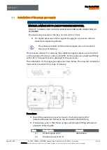
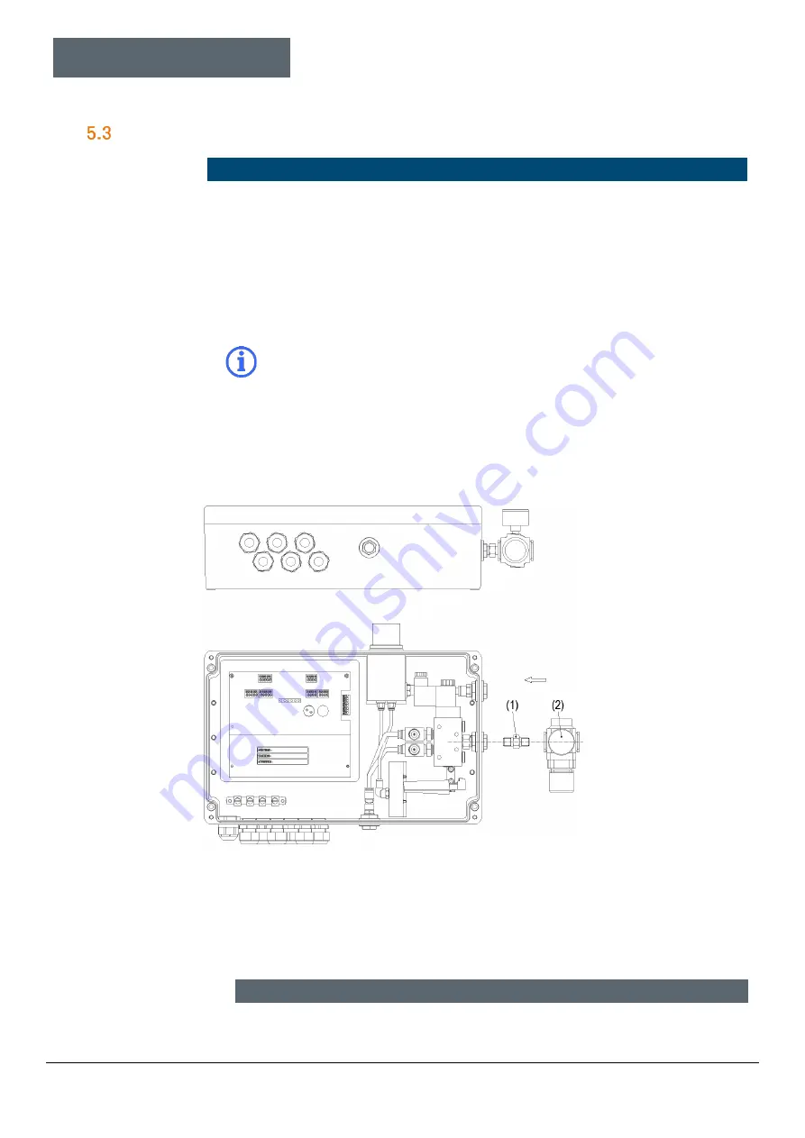
The pressure reducer for reducing the supplied purge gas pressure is mounted
on the outside of the Ex p control unit APEX. For this purpose, a bulkhead fitting
with a G1/4" internal thread is attached to the enclosure.
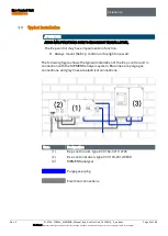
The installation of the purge gas supply is shown below. The required installation
material is included in the scope of delivery.
Procedure:
Mount the pressure reducer by means of a double nipple G1/4"
(detachable) external thread on the provided bulkhead fitting.
If necessary, glue in the thread using a suitable pipe fitting adhesive or
seal with Teflon tape®.
Item
Designation
Remark
(1)
Double nipple G1/4“
detachable
(2)
Pressure reducer G1/4“
Содержание Ex p Control Unit APEX
Страница 1: ...Manual Ex p Control Unit APEX Set SIEMENS ...

