Electrical connections
Ex p Control Unit
SIEMENS Set
Page 42 of 80
01-37A2-7D0004_SIEMENS_Manual_Exp-Control-Unit_20220216_0_en.docx
Rev. 0
Disclaimer: We reserve the right to make technical changes. Changes, errors and printing errors do not justify claims for damages.
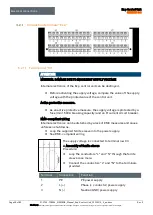
6.2.2.3
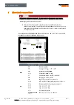
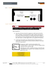
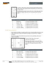
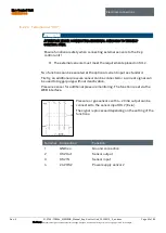
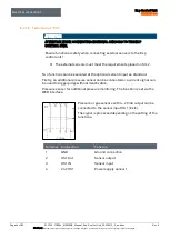
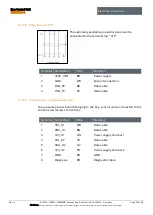
Terminal row “X16“
WARNING
RISK OF DEATH OR INJURY DUE TO UNINTENTIONAL ALTERATION OF THE
EX-RELEVANT PARAMETERS.
Explosion protection is no longer guaranteed.
Remove the programming enable again after deliberately changing
parameters.
After changing or adapting parameters, a subsequent functional test
must be performed.
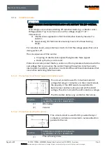
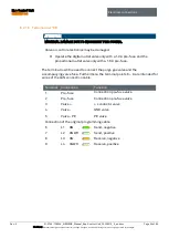
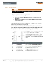
The programming enable must be connected and activated in order to change
settings and setpoint values on the device.
It must only be connected during the deliberate modification of parameters.
After changing or adapting parameters, a final function test must be performed.
During normal operation of the Ex p system it may not be connected.
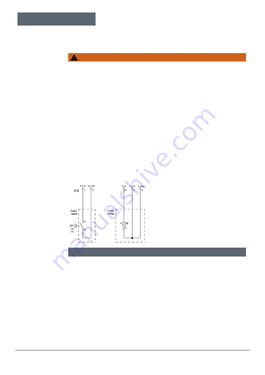
The BARTEC parameter-setting switch must
be used to change the parameters.
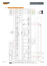
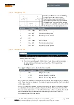
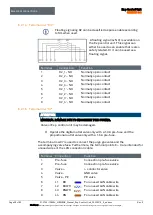
The temperature sensor can be a PT 100 or
1000. Settings for the sensor are made in
the device. Two or three wire sensors can be
used.
Terminal
Connection
Function
1
Parameter IN
Contact for the parameter setting switch
2
Parameter OUT
Contact for the parameter setting switch
3
T sensor 3 IN
Temperature sensor connection
4
T sensor 3 OUT
Temperature sensor connection
5
T sensor 3 MESS
Temperature sensor connection
Содержание Ex p Control Unit APEX
Страница 1: ...Manual Ex p Control Unit APEX Set SIEMENS ...

