82
5.6.6 Lightbox Replacement
•
Remove the reel drum as described in Sect. 5.6.2.
•
Note the position of the lightbox position marker against the –90 to +90 scale on the
frame.
•
Note the position of all lampholders relative to each other and to the lightbox.
•
Remove all lampholders as described in Sect. 5.6.3, but do not disconnect the wiring.
•
Slide the lightbox round the guide channel to remove it from the reel assembly frame.
5.6.7 Fitting the lightbox
•
Slide the lightbox onto the guide channel so that the tongue at each end of the lightbox
enters the groove. Lift the centre tab slightly to allow proper fitting.
•
Slide the lightbox to place the lightbox position marker at the position noted at step (2)
of the removal procedure.
•
Offer each lampholder to the lightbox, in the position noted at step (3) in section 5.7.3
of the removal procedure, then gently press the lampholder into its aperture until it
snaps into position.
5.6.8 Opto replacement
5.6.8.1 Removing the opto
•
Remove the reel drum as described in Sect. 5.6.2
•
Note the position of the opto on the reel assembly frame by observing the opto marker
scale reading.
•
Remove and retain the cross head screw securing the opto to the reel assembly
frame.
•
Note the position of colour coded electrical connections to the opto 3-way I.D.C.
connector. Use needle nosed pliers to disconnect the wiring, then withdraw the opto.
5.6.8.2 Refitting the opto
•
Use an appropriate I.D.C. insertion tool to connect wiring to the opto connector, in the
positions noted at step (4) above.
•
Fit the opto to the frame, using the cross head screw, and adjust the opto position for
the scale reading as noted in step (2) above.
•
Note ...
The tables below show the correct relationship between the lightbox and opto settings for front
and rear door machines using 16 and 24 symbol reels.
•
Fit the reel drum as described in Sect. 5.6.3.
Содержание MPU6
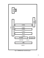
Страница 73: ...73 Fig 37 MUX5 board connector layout...


