


66
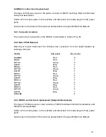
4.24.4 STROBE Signals
The strobe signals STROBE1 and STROBE2 are provided for games which require a strobe
light to flash, synchronised to the reel steps so as to provide animation as seen by the player.
For machines using strobe signals, these are output via a 6-way STROBE connector having
a keyway at pin position 3.
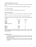
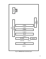
4.24.5 Barbus interface
Power supplies and serial communications are interfaced to the REEL5 control board via a
Barbus interface which is identical to that on the MUX5(E) board and is described in Sect.
4.3.4. The Barbus is interfaced via a red 11-way BARBUS connector having a keyway at pin
position 7.
4.24.6 Power
A green LED located adjacent to the REEL5 motor connector indicates a healthy status of
the +34V supply.
4.24.7 Communications
A bi-colour STATUS red/green LED is located midway between the REEL4 and LAMP4
connectors. The LED functions exactly as described in Sect. 4.3.7 for the MUX5(E) board.
4.24.8 troubleshooting
This section contains information to aid the service engineer to isolate faulty machine
modules.
4.24.9 Initialisation self test (Door Open)
The procedure for initialisation self testing is contained in the machines program. Briefly, the
test procedure is as follows:
If the machine is a UK machine the alphanumeric firstly displays INITIALISING, then
manufacturer name followed by the machines four letter ident code, including the version
number. The machine jackpot and percentage settings are then followed by the SEC meter
entry menu.
If the cabinet doors are closed, the alpha display then shows the price of play setting and the
machines four letter ident code
Finally, the reels are tested by being spun for two revolutions, coming to rest at their last play
positions.
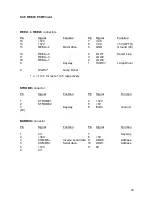
Содержание MPU6
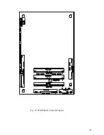
Страница 73: ...73 Fig 37 MUX5 board connector layout...


