58
4.19 Buttons interface
The MUX5(E) board can interface with 16 illuminated pushbuttons via a brown 13-way
BUTTONS connector having a keyway at pin position 11.
The interface's lamps and switches are each wired into a 2 x 8 matrix as shown in Fig. 29.
The diode in the switch input line protects the transistor a34V which might appear on
the line under certain fault conditions.
Select line
BLUE
Select lines
From cpu
To current
sensing
circuits
+34V
LAMP DRIVE
TRANSISTOR
(1 of 2)
Lamp drive
GREEN
1.0 ohm
From cpu
2nd lamp
drive
+5V
Switch input
To cpu
2nd switch input
13
12
KEY
(11)
2
1
3
4
5
6
7
8
9
10
BUTTONS
SWITCH DRIVE
TRANSISTOR
(1 of 2)
SELECT
TRANSISTOR
(1 of 8)
Fig. 29. Buttons interface
Содержание MPU6
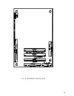
Страница 73: ...73 Fig 37 MUX5 board connector layout...


