


89
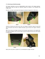
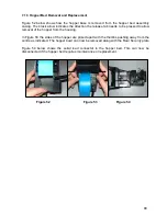
7.1.3 Hopper Bed Removal and Replacement
Figure 52 below shows how the hopper base is removed from the hopper bed assembly
casing. The black arrow indicates the direction the release tab needs to be pressed to allow
removal of the hopper from the housing.
In Figure 53 the sides of the hopper are prised apart with the thumbs pushing away from the
centre as indicated. The hopper bowl can now be removed along with the Rear Security plate
Figure 54 below shows the serial lead connector to the hopper bed. This can now be
disconnected if the hopper bed requires maintenance or replacement.
Figure
52
Figure
53
Figure
54
Содержание MPU6
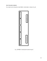
Страница 73: ...73 Fig 37 MUX5 board connector layout...


