


23
3.3 Port Information
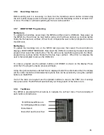
The MPU6 board is a single board controller comprising of a microprocessor, memory,
Barbus power/data link, 2 x USB ports, SP/DIF input, Dataport, Stakes & prizes &
percentage key sockets.
The 64 way port connector is used for driving numerous peripheral devices and for receiving
inputs from switches and pushbuttons etc. There is an additional connector from this to
provide expansion for further functionality as required.
To interface to the outside world these connectors are mounted around the periphery of the
unit, ensuring good mechanical support when plugging or unplugging thus minimising flexing
of the PCB. The MPU6 board and its enclosure are fixed to the cabinet via two M4 screws.
The MPU6 unit has the following connections & functionality.
3.3.1 Barbus
interface
The proprietary Barbus is a combined power bus and serial data link connected in a daisy
chain layout between the machine modules. The Barbus is connected to the MPU6 board via
a red 11-way BARBUS connector.
3.3.2 Power Status Indicators
The power status indicators monitor the supply rails to ensure the correct operating voltages
are present. In normal operation all LEDs should be lit, in the event that one of the supply
voltages has failed the appropriate led will not illuminate.
3.3.3 64 WAY Input/Output connector
The 64 way connector drives numerous peripheral devices such as the note acceptor, ticket
printer, meters, CCtalk devices and is used for receiving inputs from switches and
pushbuttons etc. This port also has an expansion connector for future use as required.
3.3.4 S/P DIF Output
The S/PDIF interface (Sony Philips Digital Interface), is used to provide compressed digital
audio for the machines stereo speakers. Also it can receive external audio from other
equipment and played through the machines stereo speakers.
3.3.5 Sixteen Segment LCD display
The LCD display shows the current status of the MPU6, in the event of a peripheral device
failure such as a ‘coin mech jam’ the appropriate error message will be shown on the display.
(Please refer to section 3.4 for MPU6 6 fault codes).
Содержание MPU6
Страница 73: ...73 Fig 37 MUX5 board connector layout...


