


32
3.5
MPU6 TEST JIG
The procedures for bench testing the MPU6 independently with the aid of a test jig are
contained in this section. The test jig is designed to enable independent testing of the MPU6
CPU, switches and port functionality.
3.5.1 Overview
The functional testing of MPU6 is carried out using a test jig. In conjunction with the MPU6
internal test software, enables testing of board interfaces, communications facilities and the
central processor.
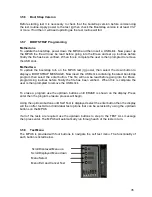
The test jig comprises of a panel containing blocks of switches, LED’s and Alpha display to
represent those on a gaming machine and a wiring harness and USB connectors which plug
into headers on the board under test.
When a board is connected to a test jig and power is applied, all board outputs are
exercised. All inputs are polled, so any change of input gives a visual status indication on the
test jig panel.
These instructions are intended as a guide to enable independent testing of the MPU6 functionality.
Before starting the test ensure that Bootstrap version 3.7 or greater is installed on the MPU6 or the
functionality test cannot be completed. This can be checked by powering on the unit and then check the
MPU6 Alpha Display.
3.5.2 Kit
Contents
•
MPU6 loopback test panel.
•
USB A to B Lead.
•
Switch Mode Power Supply Unit.
•
Mains Cable.
•
Barbus Power supply harness.
•
MPU6 64-Way Test Link Ribbon Cable.
•
MPU6 D-Type Test PCB.
•
Test Instruction Sheet.
Содержание MPU6
Страница 73: ...73 Fig 37 MUX5 board connector layout...


