68
SECTION 5
5.1 MPU6 board replacement
Switch off the mains power to the machine and disconnect the mains plug from the power
point.
Gain access to the interior of the machine as described in the specific Machine Manual.
5.1.1 MPU6 Connectors
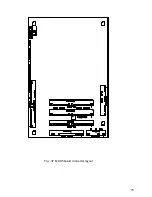
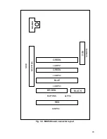
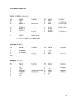
The location of all connectors on the MPU6 board is shown in Fig. 5.
5.1.2 MPU6 Removal
Disconnect the connectors lifted below where fitted before removing the MPU6 unit from the
machine.
•
USB A Connector
•
USB B Connector
•
Barbus Connector
•
SP/DIF connector
•
64 way I/O connector by releasing the connector using the tabs.
•
25-way Dataport Connector.
Remove the MPU6 from it’s mounting by removing the two mounting screws located to the
left and right hand sides of the case.
5.1.3 MPU6 Refitting
Place the MPU6 in position over the mounting holes and screw the two mounting screws to
secure it place. Now replace each of the previously removed connectors in their correct
positions.
Содержание MPU6
Страница 73: ...73 Fig 37 MUX5 board connector layout...


