


PARTNER
®
Advanced Communications System Installation, Programming, and Use
Installing the Control Unit
2-8
Wall-Mounting a 5-Slot Carrier and Modules
2
Install the 5-slot carrier within 5 feet (1.5 meters) of a properly grounded wall outlet (not
controlled by a switch) and the network interface jacks. When you mount the carrier on the wall,
leave at least 1 foot (0.3 meter) of clearance at the top and sides, and 2 feet (0.6 meter) at the
front and bottom to ensure proper ventilation.
For a 5-slot carrier, you need four #12 screws of the appropriate type for the wall and weight of
the control unit (a control unit with four expansion modules and a processor module weighs
approximately 31 pounds or 14 kilograms). The weight of other configurations may vary slightly.
Follow these steps to wall-mount the 5-slot carrier
and modules:
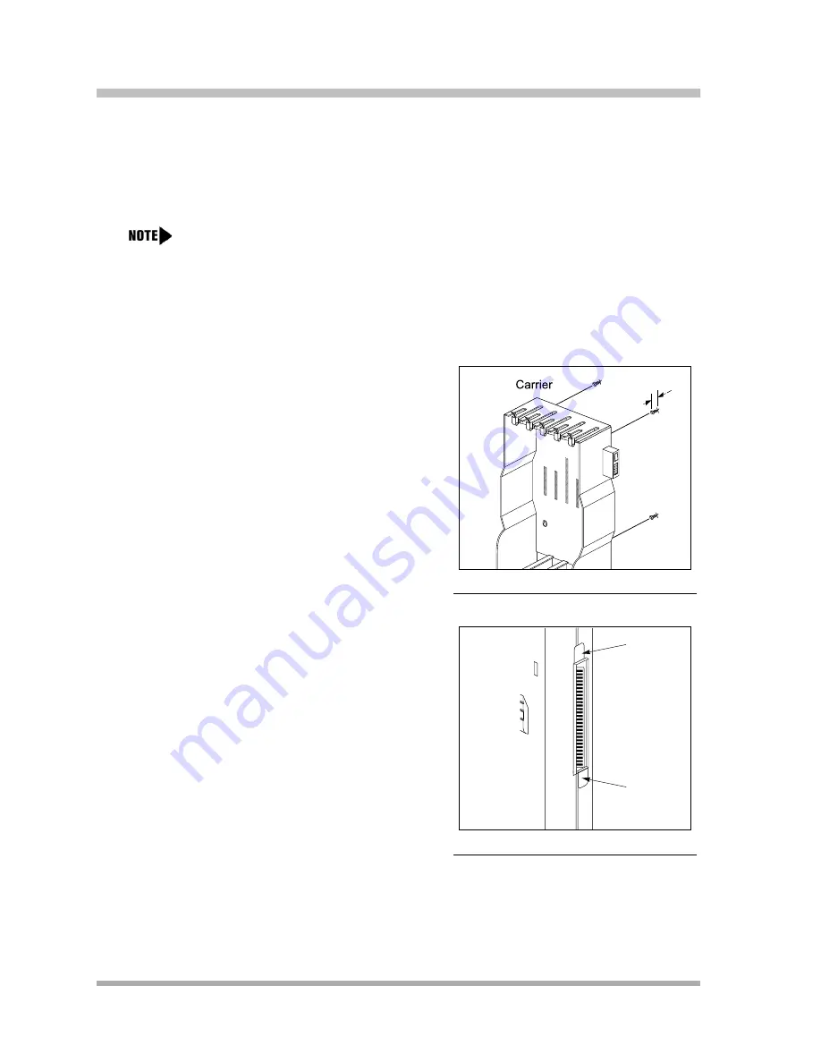
1.
Using the enclosed template, mark the screw
locations on the wall (see
). If you are
mounting the carrier on plywood, start four #12
screws supplied with the carrier, leaving the
screw heads extending approximately 1/4 inch
(0.64 cm) from the wall. If you are mounting on
drywall, use wall anchors, which must be
purchased separately.
Figure 2-8. Mounting Screw Locations
2.
Before installing any modules, make sure the
clear, plastic protector has been removed from
the connector area on the rear of each module.
To remove the protector, grasp the tabs on the
ends of the protector and lift (see
).
3.
Insert the PARTNER ACS processor module in
the center slot of the carrier.
Figure 2-9. Removing the Plastic
Protector
The location of each module within the carrier is important; place the modules as
instructed in the following procedure.
1
4
"
Tab
Tab
Содержание programming and use
Страница 10: ...PARTNER Advanced Communications System Installation Programming and Use viii Master TOC...
Страница 12: ...PARTNER Advanced Communications System Installation Programming and Use 1 ii...
Страница 30: ...PARTNER Advanced Communications System Installation Programming and Use System Components 1 18...
Страница 32: ...PARTNER Advanced Communications System Installation Programming and Use 2 ii...
Страница 74: ...PARTNER Advanced Communications System Installation Programming and Use 3 ii...
Страница 94: ...PARTNER Advanced Communications System Installation Programming and Use Emergency Phone Number List 406 3 20...
Страница 168: ...PARTNER Advanced Communications System Installation Programming and Use Voice Interrupt On Busy 312 4 70...
Страница 170: ...PARTNER Advanced Communications System Installation Programming and Use 5 ii...
Страница 178: ...PARTNER Advanced Communications System Installation Programming and Use 6 ii...
Страница 210: ...PARTNER Advanced Communications System Installation Programming and Use Handling Calls 6 32...
Страница 212: ...PARTNER Advanced Communications System Installation Programming and Use 7 ii...
Страница 314: ...PARTNER Advanced Communications System Installation Programming and Use Voice Mailbox Transfer F14 8 76...
Страница 366: ...PARTNER Advanced Communications System Installation Programming and Use 10 ii...
Страница 390: ...PARTNER Advanced Communications System Installation Programming and Use 11 iv...
Страница 430: ...PARTNER Advanced Communications System Installation Programming and Use A 10...
Страница 436: ...PARTNER Advanced Communications System Installation Programming and Use Speed Dial Form C 4...
Страница 440: ...PARTNER Advanced Communications System Installation Programming and Use Overview D 4...
Страница 468: ...PARTNER Advanced Communications System Installation Programming and Use IN 14...