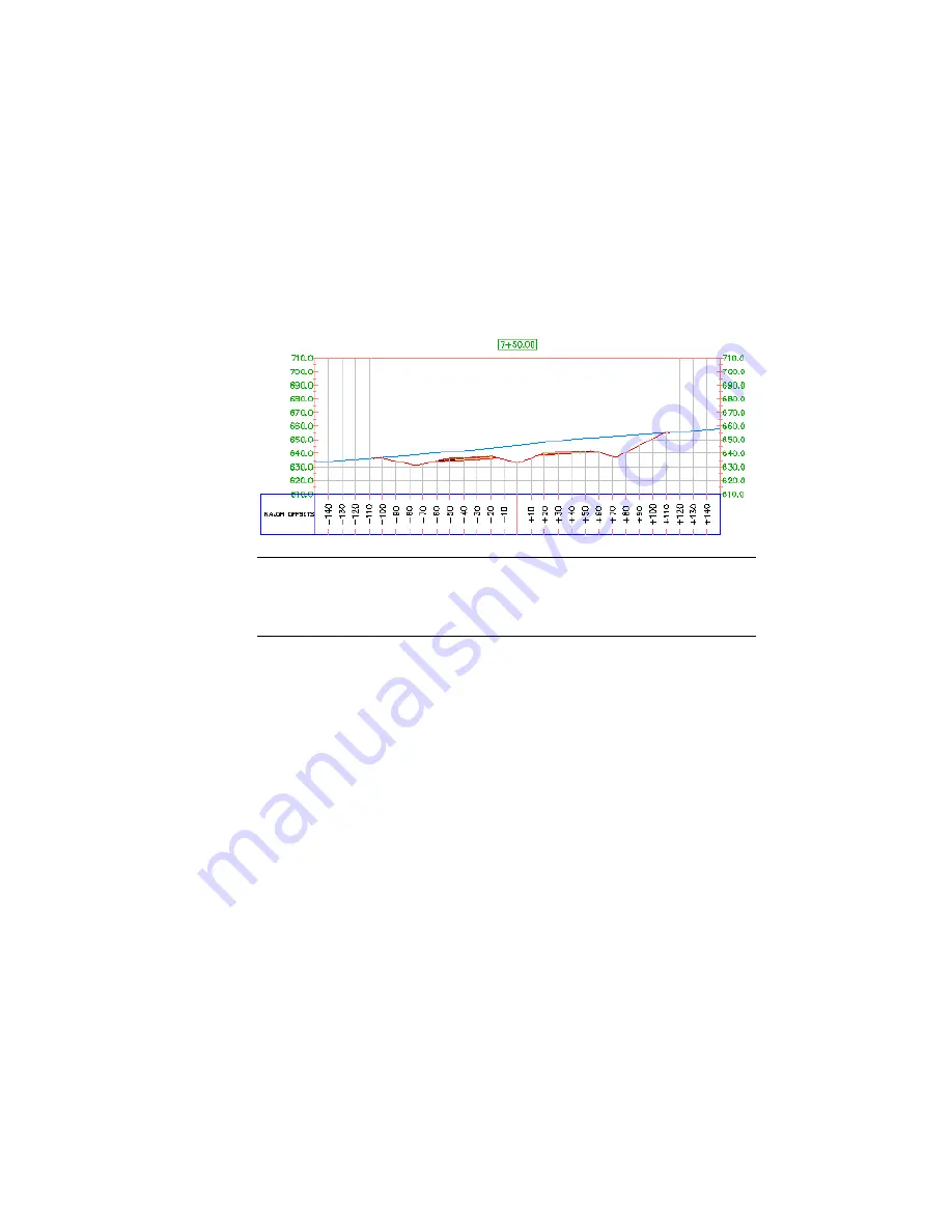
Cross sections show elevations at sample lines, which are created perpendicular
to an alignment. Sections can be derived from surfaces, corridors models, and
corridor surfaces. Furthermore, they can be either dynamic or static. When a
surface or corridor is modified, dynamic sections are automatically updated.
A static section shows the elevations at the time it was created, but does not
react to later geometry changes. Similarly, dynamic sample lines associated
with an alignment move with the alignment if it is modified.
TIP
You can use the workflow that is demonstrated in this tutorial to create section
views from a corridor Xref. Section views created from an Xref can be dynamically
linked to the corridor model; if the corridor model in the Xref drawing changes,
the section views update automatically.
For more information, see the AutoCAD Civil 3D Help topic Sections.
Exercise 1: Creating Sample Lines
In this exercise, you will create a set of sample lines along the alignment.
The sample lines define the stations at which the cross sections are cut, and
also the width of the sections to the left and right of the alignment. A set of
sample lines is stored in a Sample Line Group for the alignment. Each sample
line group has a unique name. Each line within the group also has a unique
name.
For more information, see the AutoCAD Civil 3D Help topic Creating and
Editing Sample Lines and Sections.
Create sample lines
1
Open Sections-Sample-Lines-Create.dwg, which is located in the
tutorial
drawings folder
(page 819)
.
570 | Chapter 15 Sections Tutorials
Содержание AUTOCAD PLANT 3D 2011 - SYSTEM REQUIREMENTS
Страница 1: ...AutoCAD Civil 3D 2011 Tutorials April 2010 ...
Страница 58: ...46 ...
Страница 70: ...58 ...
Страница 73: ...Tutorial Creating and Adding Data to a Surface 61 ...
Страница 140: ...128 ...
Страница 370: ...6 Press Enter to create the parcel The new parcel is created and labeled 358 Chapter 10 Parcels Tutorials ...
Страница 376: ...5 Specify the parcel frontage as shown in the following image 364 Chapter 10 Parcels Tutorials ...
Страница 378: ...7 Press Enter 366 Chapter 10 Parcels Tutorials ...
Страница 382: ...5 Specify the parcel frontage as shown in the following image 370 Chapter 10 Parcels Tutorials ...
Страница 385: ...8 Press Enter Exercise 2 Swinging One End of a Parcel Lot Line 373 ...
Страница 432: ...420 ...
Страница 470: ...458 ...
Страница 506: ...494 Chapter 13 Corridors Tutorials ...
Страница 559: ...4 Click Road D which is to the north of the roundabout Exercise 2 Adding an Approach Road to a Roundabout 547 ...
Страница 580: ...568 ...
Страница 668: ...656 ...
Страница 674: ...15 Click View tab Views panel Front Four profiles from front view are displayed 662 Chapter 18 Part Builder Tutorials ...
Страница 678: ...23 Change your view to SW isometric 666 Chapter 18 Part Builder Tutorials ...
Страница 679: ...24 Change your visual style to Conceptual Exercise 2 Defining the Manhole Geometry 667 ...
Страница 706: ...694 Chapter 18 Part Builder Tutorials ...
Страница 743: ...11 Repeat this step for the inner box extrusion Dimension Len B4 is created Exercise 4 Finalizing the Part 731 ...
Страница 830: ...818 ...
Страница 832: ...tutorial folder AutoCAD Civil 3D installation location Help Civil Tutorials 820 Glossary ...


