following steps, you will override the Design Value at the current station,
and then examine the results.
6
Change the Width Value to 36.0000’.
Notice that the Override check box is automatically selected, which
indicates that the Design Value has been overridden at this station.
7
Click
Go To Next Station several times.
Notice that for the other stations, the Width Value is 12.000’. The lane
subassembly that is displayed in the section view updates in width to
reflect the width at the current station.
8
On the Station Selection panel, in the Select A Station list, select 7+75.00.
9
In the Corridor Parameters dialog box, in the Assembly - (1) tree, under
Group - (1), under Lane (Right), in the Width row, clear the Override
check box.
The Value column displays the same value as the Design Value column.
Modify subassembly properties for a range of stations
1
On the View Tools panel, click
Zoom To Extents.
2
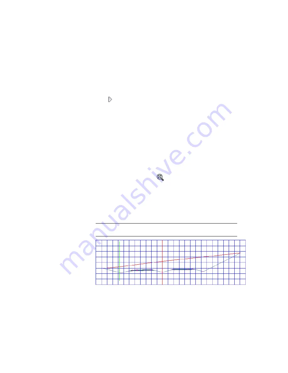
On the Station Selection panel, in the Select A Station list, select 4+50.00.
Notice that the road is in a shallow cut on one side and deep cut on the
other. The criteria set for the daylight subassembly caused it to use a 6:1
slope on the left side, and a 4:1 slope on the right side. Also notice the
superelevation transition of the road. At station 4+50.00, the lanes are
relatively flat.
NOTE
For more information about superelevation, see the
Applying
Superelevation to an Alignment
(page 262) tutorial.
Exercise 2: Editing Corridor Sections | 481
Содержание AUTOCAD PLANT 3D 2011 - SYSTEM REQUIREMENTS
Страница 1: ...AutoCAD Civil 3D 2011 Tutorials April 2010 ...
Страница 58: ...46 ...
Страница 70: ...58 ...
Страница 73: ...Tutorial Creating and Adding Data to a Surface 61 ...
Страница 140: ...128 ...
Страница 370: ...6 Press Enter to create the parcel The new parcel is created and labeled 358 Chapter 10 Parcels Tutorials ...
Страница 376: ...5 Specify the parcel frontage as shown in the following image 364 Chapter 10 Parcels Tutorials ...
Страница 378: ...7 Press Enter 366 Chapter 10 Parcels Tutorials ...
Страница 382: ...5 Specify the parcel frontage as shown in the following image 370 Chapter 10 Parcels Tutorials ...
Страница 385: ...8 Press Enter Exercise 2 Swinging One End of a Parcel Lot Line 373 ...
Страница 432: ...420 ...
Страница 470: ...458 ...
Страница 506: ...494 Chapter 13 Corridors Tutorials ...
Страница 559: ...4 Click Road D which is to the north of the roundabout Exercise 2 Adding an Approach Road to a Roundabout 547 ...
Страница 580: ...568 ...
Страница 668: ...656 ...
Страница 674: ...15 Click View tab Views panel Front Four profiles from front view are displayed 662 Chapter 18 Part Builder Tutorials ...
Страница 678: ...23 Change your view to SW isometric 666 Chapter 18 Part Builder Tutorials ...
Страница 679: ...24 Change your visual style to Conceptual Exercise 2 Defining the Manhole Geometry 667 ...
Страница 706: ...694 Chapter 18 Part Builder Tutorials ...
Страница 743: ...11 Repeat this step for the inner box extrusion Dimension Len B4 is created Exercise 4 Finalizing the Part 731 ...
Страница 830: ...818 ...
Страница 832: ...tutorial folder AutoCAD Civil 3D installation location Help Civil Tutorials 820 Glossary ...


