SRV-63 series AC servo drives Commissoning
-212-
Motor
Torque
command
P1.29
P1.30
P2.04
P1.31
P1.32
P2.03
P2.00
P2.01
P2.05
P1.33
P1.34
P2.09
P2.08
P0.06
P0.07
P0.08
P1.23
P1.24
P1.25
P1.26
P1.27
P1.28
P1.19
P1.20
P2.20
P2.31
P2.33
P2.34
P2.32
P0.67
P0.46
P0.47
P0.48
P0.49
P0.66
P3.23
P3.24
P0.62
P3.25
P0.63
P0.65
P4.14
P4.10
P3.70
P3.71
P3.72
P0.61
P0.60
P4.53
P0.68
Encoder
Internal
speed limit
command
External
speed limit
command
Current
controller
Gain
switching
Frequency
division output
Torque limit
Torque filter
Notch filter
Speed
controller
Torque
command
selection
Torque
command
Ramp
Speed
detection
filter
Speed limit
selection
Internal
torque
command
Analog
torque
command
Communication
bus torque
command
P3.73
P3.74
P3.75
P3.76
P1.02
P1.01
P2.06
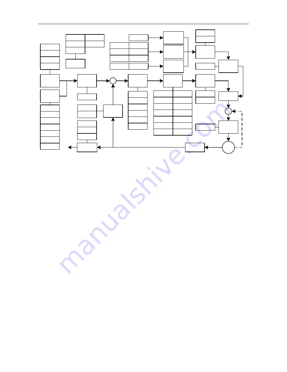
The general procedures for parameter adjustment in the torque mode are:
1) Initial setting of the parameters
The defaults of the parameters can be recovered by the default parameter recovering operation (see
chapter 5.2.5.3 for details).
2) Adjustment of the torque smoothing filter
In the case the analog torque command is inputted, we can adjust the torque smoothing filter time
constant to make the torque change smoothly.
3) Frequency division of the feedback pulse output
If the feedback pulse of the encoder needs to be outputted, the frequency division coefficient of pulse
output can be used to change the frequency of the output pulse.
7.2.4 Fully-closed loop gain adjustment
The gain parameters which can be adjusted are listed as the figure below:


