Cycle Timings and Interlock Behavior
ARM DDI 0363E
Copyright © 2009 ARM Limited. All rights reserved.
14-6
ID013010
Non-Confidential, Unrestricted Access
14.2
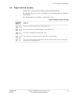
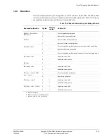
Register interlock examples
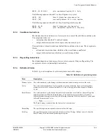
Table 14-2 shows register interlock examples using
LDR
and
ADD
instructions.
LDR
instructions take one cycle, have a result latency of two, and require their base register as a
Very Early Reg.
ADD
instructions take one cycle and have a result latency of one.
Table 14-2 Register interlock examples
Instruction
sequence
Behavior
LDR R1, [R2]
ADD R6, R5, R4
Takes two cycles because there are no register dependencies.
ADD R1, R2, R3
ADD R9, R6, R1
Takes two cycles because
ADD
instructions have a result latency of one.
LDR R1, [R2]
ADD R6, R5, R1
Takes three cycles because of the result latency of R1.
ADD R2, R5, R6
LDR R1, [R2]
Takes four cycles because of the use of the result of R2 as a Very Early Reg.
LDR R1, [R2]
LDR R5, [R1]
Takes four cycles because of the result latency of R1, the use of the result of R1 as a Very Early Reg,
and the use of an LDR to generate R1.


