Debug
ARM DDI 0363E
Copyright © 2009 ARM Limited. All rights reserved.
11-20
ID013010
Non-Confidential, Unrestricted Access
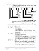
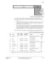
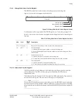
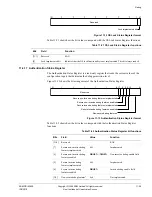
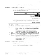
Figure 11-7 Vector Catch Register format
If one of the bits in this register is set and the instruction at the corresponding vector is
committed for execution, the processor either enters debug state or takes a debug exception.
Note
•
Under this model, any prefetch from an exception vector can trigger a vector catch, not
only the ones because of exception entries. An explicit branch to an exception vector
might generate a vector catch debug event.
•
If any of the bits are set when the processor is in Monitor debug-mode, then the processor
ignores the setting and does not generate a vector catch debug event. This prevents the
processor entering an unrecoverable state. The debugger must program these bits to zero
when Monitor debug-mode is selected and enabled to ensure forward-compatibility.
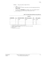
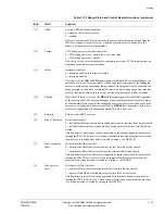
Table 11-13 shows how the bit values correspond with the Vector Catch Register functions.
31
8 7 6 5 4 3 2 1 0
Reserved
Reset
Reserved
SVC
Prefetch abort
Data abort
Reserved
IRQ
FIQ
Table 11-13 Vector Catch Register functions
Bits
Field
Reset
value
Normal
address
High vectors
address
Function
Access
[31:8]
Reserved
0
-
-
Do not modify on writes. On reads,
the value returns zero.
RAZ or
SBZP
[7]
FIQ
0
0x0000001C
0xFFFF001C
Vector catch enable.
RW
[6]
IRQ
-
0x00000018
a
0xFFFF0018
a
Vector catch enable.
-
[5]
Reserved
0
-
-
Do not modify on writes. On reads,
the value returns zero.
RAZ or
SBZP
[4]
Data Abort
0
0x00000010
0xFFFF0010
Vector catch enable.
RW
[3]
Prefetch Abort
0
0x0000000C
0xFFFF000C
Vector catch enable.
RW
[2]
SVC
0
0x00000008
0xFFFF0008
Vector catch enable.
RW
[1]
Reserved
0
0x00000004
0xFFFF0004
Vector catch enable, Undefined
instruction.
RW
[0]
Reset
0
0x00000000
0xFFFF0000
Vector catch enable.
RW
a. If the VIC interface is enabled, the address is the last IRQ handler address supplied by the VIC, whether or not high vectors
are in use.


