User Manual
KDC Series II DC Power Supplies
49
4.3 How to examples...
This section covers some common tasks that are often performed with an DC power supply.
These examples are written in a How to... format and provide step by step instructions on how to
set up the DC supply for a specific task.
4.3.1
Set the Output
Output parameters are Voltage and Current Limit.
1. Disable the output by pressing the OUTPUT button. The LED above the button will turn off.
2. Press the SET button if the PROGRAM screen is not visible.
SLEW MODE
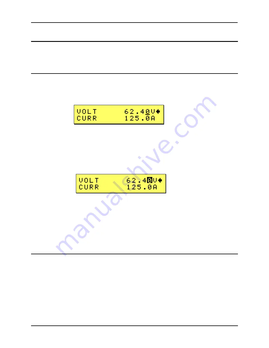
3. Use the left shuttle to change the displayed output voltage setting. Clockwise will increase the
setting, counter clockwise will reduce the setting. The LCD display will show the voltage
setting. The output will change as the setting changes. This is called the slew mode of
operation.
4. Alternatively, you can use the SET mode. The set mode is entered by pressing the SET key
again while the PROGRAM screen is visible. Once in SET mode cursor will blink on/off until
the ENTER key is pressed, indicated a new set value has been dialed in but not yet entered.
SET MODE
5. While in SET mode, changing the voltage setting will not affect the output until ENTER is
pressed. To cancel the SET mode, either press ENTER to update the output with the new
voltage setting or press the SET key again to return to the slew mode.
6. Use the right shuttle to set the current limit. The setting will blink on/off until the ENTER key is
pressed, indicating a new set value has been dialed in but not yet entered.
7. Enable the output by pressing the OUTPUT button.
8. Press the ENTER button to activate the new settings.
4.3.2
Display Measurement Data
Measurements are always active and can be displayed as follows:
1. Press the MEASURE button located below the LCD display.
2. All measurements are displayed on the LCD screen.
Содержание KDC 100-100
Страница 2: ......
Страница 10: ......
Страница 26: ...User Manual 16 KDC Series II DC Power Supplies Figure 3 1 Location of rear panel connectors ...
Страница 33: ...User Manual KDC Series II DC Power Supplies 23 Figure 4 3 Front panel layout ...
Страница 82: ......
Страница 83: ...User Manual KDC Series II DC Power Supplies 73 Figure 6 1 DC Power Supply Block Diagram ...
Страница 84: ...User Manual 74 KDC Series II DC Power Supplies Figure 6 2 DC Power Supply Block Diagram with IF option ...
Страница 111: ...User Manual KDC Series II DC Power Supplies 101 Figure 8 2 Replaceable Fuse Locations ...


