168
Chapter 5
Functional Testing
Phase Noise
7. Reset the UUT parameters to measure the phase noise by
performing the following steps:
a. Press
Meas Setup
,
Res BW
, 5,
Hz
.
b. Press
Meas Setup
,
More
until (2 of 2) is displayed,
Advanced
,
ADC Range
, and
Auto
.
c. Press
Meas Setup
,
More
until (2 of 2) is displayed,
Advanced
, and
Pre-ADC BPF
, until On is underlined.
d. Press
Marker
,
Function
, and
Noise
.
8. If the trace is not on the display, adjust the amplitude reference
value by pressing
Amplitude
and
Ref Value
. Then use the RGB knob to
adjust the reference value to bring the trace onto the display.
9. Perform the following steps for each frequency setting listed in Table
a. Set the signal source frequency to the value listed in the Source
Frequency column of
b. Set the center frequency on the UUT by pressing
FREQUENCY
,
Center Freq
, “n”, and
MHz
. Where “n” is the frequency value in the
Center Frequency column.
For example:
Press
FREQUENCY
,
Center Freq
, 600.010000, and
MHz
.
c. Set the noise marker frequency by pressing
Marker
, “n”, and
MHz
.
Where “n” is the frequency value in the Noise Marker Frequency
column.
For example:
Press
Marker
, 600.010000, and
MHz
.
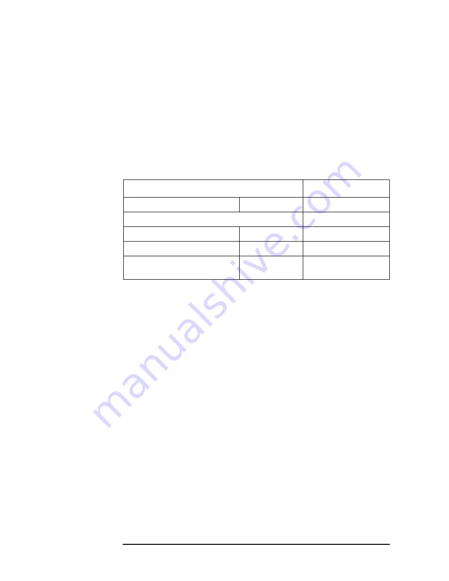
Table 5-17
UUT Initialization
Parameter
Setting
Frequency
Center
Center Frequency
Resolution Bandwidth
5 Hz
Pre ADC BPF
On/Off
On
ADC Range
Auto/On/Off
Auto
Marker
Frequency
Noise Marker
Frequency
Содержание E4406A
Страница 4: ...4 ...
Страница 10: ...10 Contents ...
Страница 138: ...138 Chapter4 Making Measurements Front Panel Test ...
Страница 139: ...139 5 Functional Testing ...
Страница 214: ...214 Chapter6 If You Have a Problem Returning Your Instrument to Agilent Technologies ...
Страница 215: ...Chapter 6 215 If You Have a Problem Repair Tag Goes Here Remove This Page Repair Tag Goes Here Remove This Page ...
Страница 216: ...216 Chapter6 If You Have a Problem Repair Tag Goes Here Remove This Page ...
Страница 217: ...217 7 Options and Accessories ...
Страница 226: ...226 Chapter7 Options and Accessories Accessories ...


